System Overview
System Overview
External Panels and Controls
Front Panel
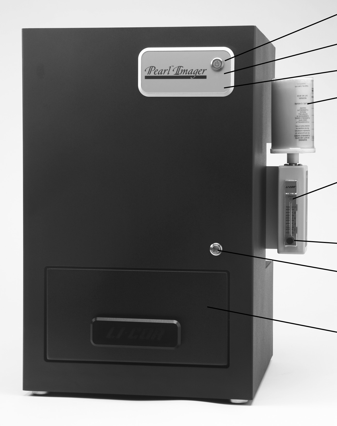 | Power on/off button |
 Image acquisition 'in progress' indicator (shown unlit) | |
 Error condition indicator (unlit) | |
| |
| |
Imaging drawer open/close button | |
Imaging drawer (closed) | |
Power On/Off Button: Pressing this button momentarily turns the instrument on and off. Pressing the button for 5 seconds or more cuts power to the instrument (Routine Maintenance and Cleaning). While the instrument is starting up or shutting down, the blue indicator light in the power button blinks. When the blue indicator light is continuously on, the instrument is ready for operation.
Note: Instruments with firmware version 1.3.1 and earlier will shut down if you press the power button, even if the image acquisition light is on. On instruments with newer firmware, the red error indicator will illuminate if you press the power button while the image acquisition indicator is on. Hold down the power button to force a shut down.
Green Image Acquisition Light: This light blinks during image acquisition and is continuously on at other times, as long as communication with Image Studio™ Software is maintained. The light is off only if communication is lost or Image Studio Software is closed.
Red Error Light: The error light illuminates to indicate that a particular process could not be completed. See Routine Maintenance and Cleaning.
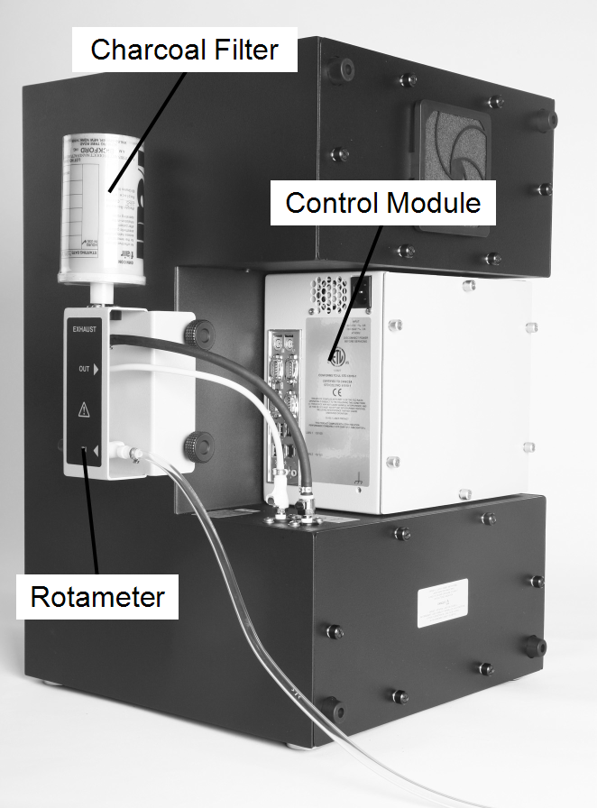
Rotameter: The rotameter provides flow control for anesthesia gas, as well as inlet connectors to receive anesthesia gas from the SmartFlow Anesthesia System or a user-supplied anesthesia system.
Scavenging Charcoal Filter: The charcoal filter removes isoflurane gas from the exhaust air stream.
Imaging Drawer Button: This button opens and closes the imaging drawer in normal operation. The drawer handle on the outside of the drawer can be used to open or close the drawer in cases of power loss or emergency.
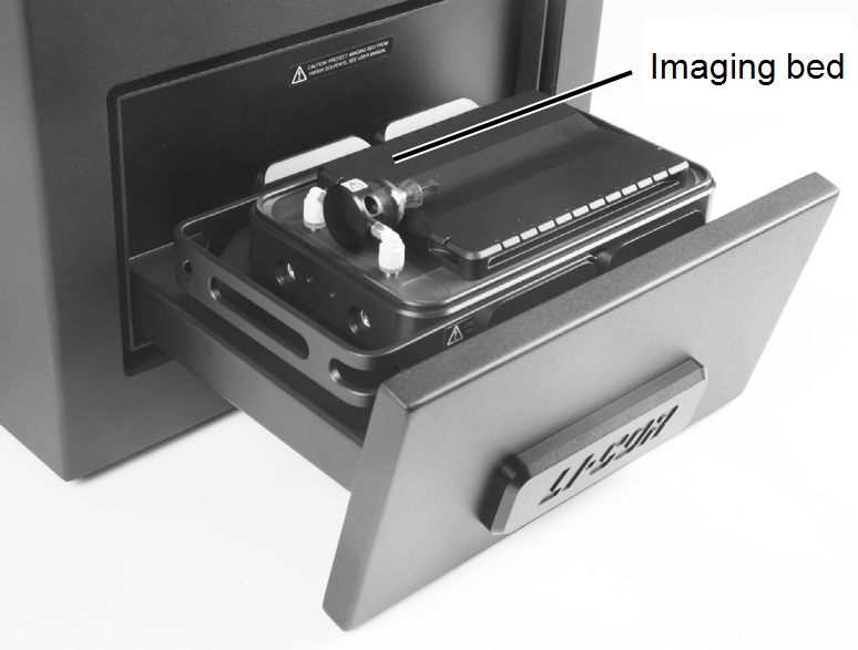
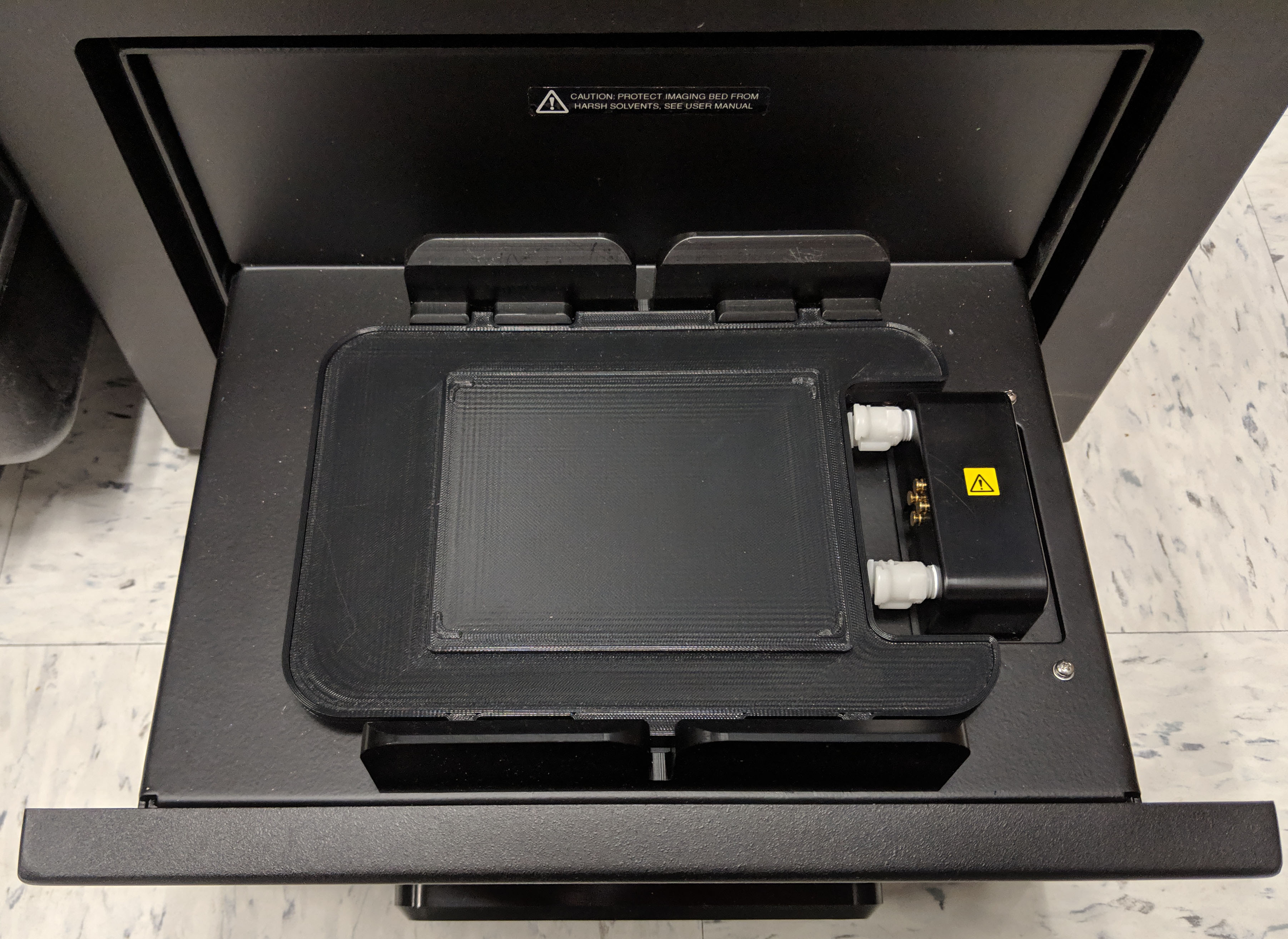
Imaging Drawer: The imaging drawer moves the
Right-side Panel
Rear Panel
| Rotameter in storage position | 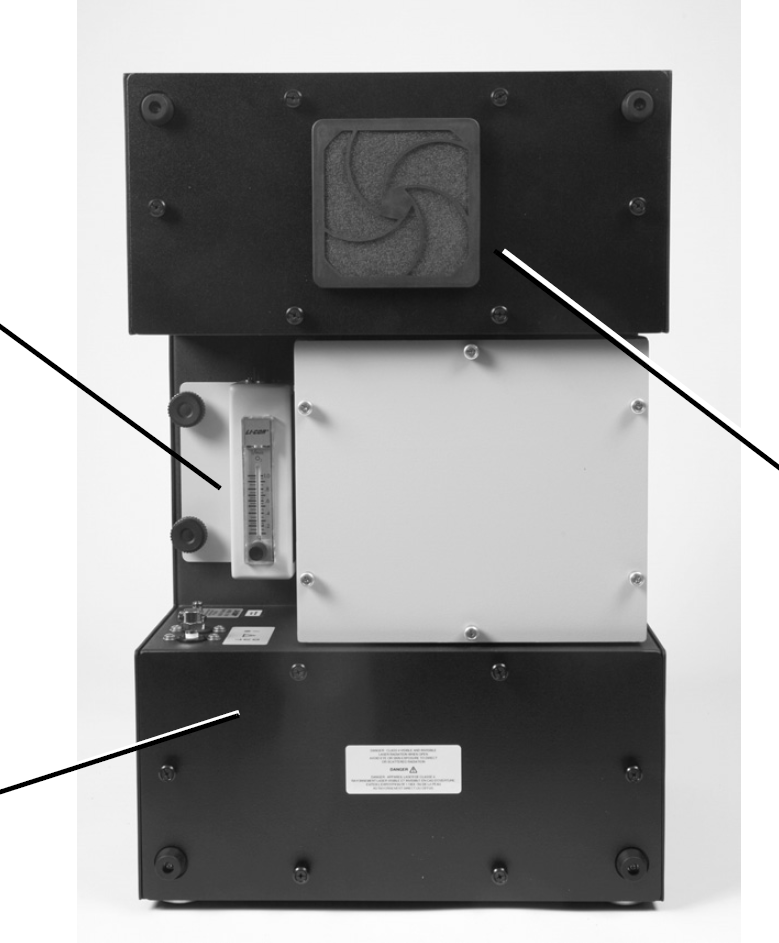 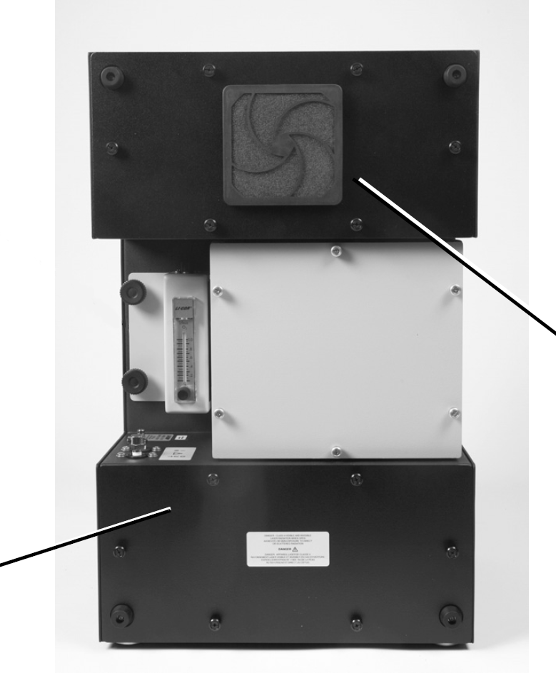 | Air fan inlet |
| Lower rear access panel |
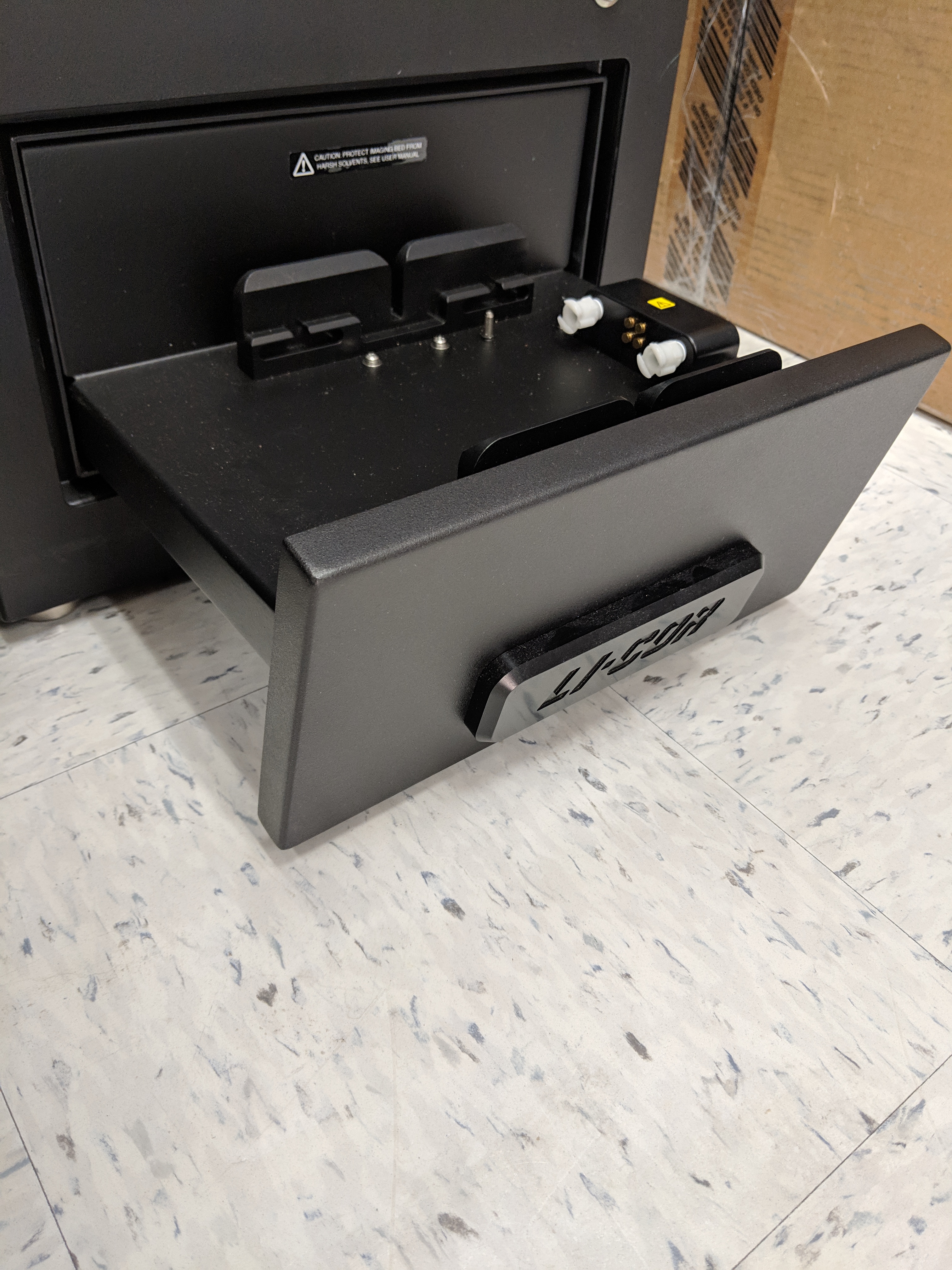
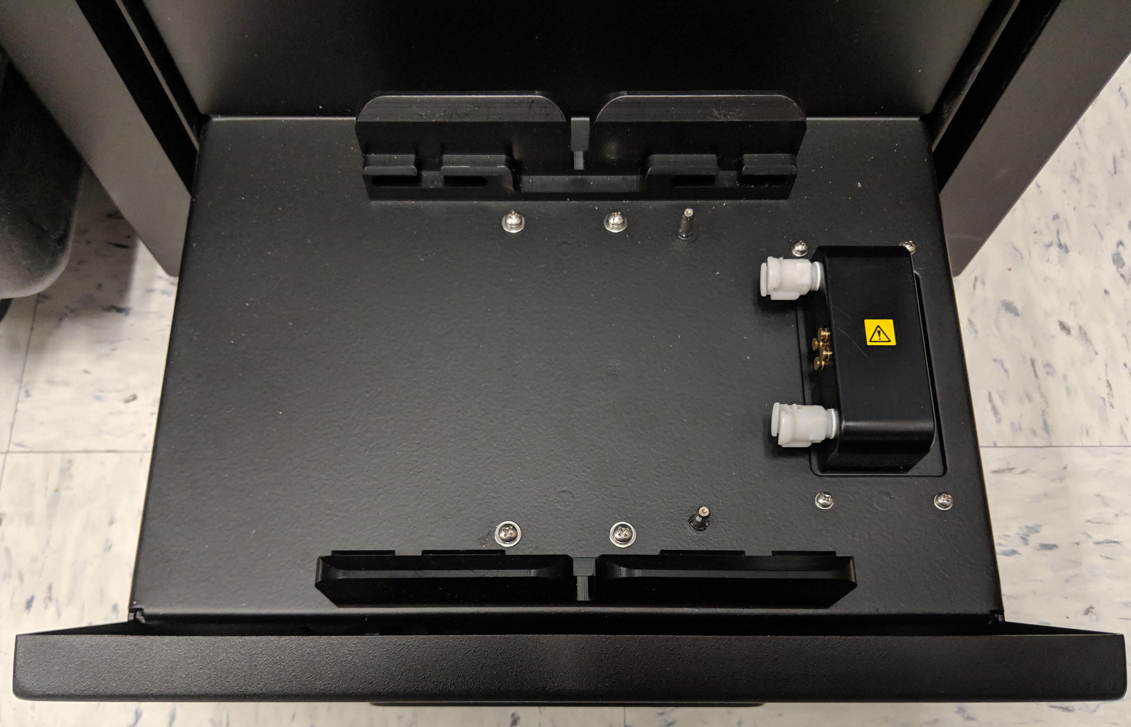
Imaging Drawer
|
Imaging Drawer Safety
Be careful not to get your fingers caught between the Pearl® Imaging System and the imaging drawer when the drawer closes. The drawer is specially designed to stop if a certain level of resistance is detected, so no harm should result, but the experience may be startling.
During an unexpected power loss, the drawer button will not function.
The imaging drawer should typically be opened and closed using the drawer button, but the drawer handle can be used to manually open or close the drawer. The drawer handle is especially useful in case of power loss or emergency.
Installing the Imaging Stage Standard Imaging Bed
Press the button above the drawer to open it.
Place the specimen on the imaging stage.
Place the imaging stage with the specimen in the drawer.
Press the button above the drawer to close it.
- Make sure the imaging bed and imaging drawer are clean and dry (Routine Maintenance and Cleaning) before starting.
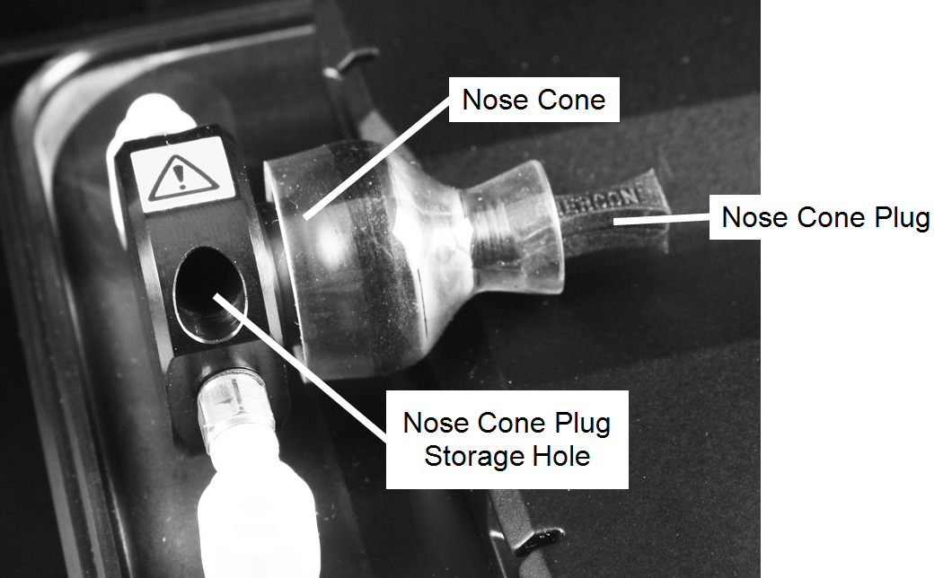
- Make sure a nose cone plug is in place in the nose cone on the imaging bed.

WARNING: If anesthesia gas is flowing to the Pearl Imager, gas will start flowing to the nose cone immediately after the imaging bed is locked in place. Make sure the nose cone plug is in place before installing the imaging bed.
AVERTISSEMENT:
Si le gaz d'anesthésie coule dans Pearl, le gaz commencera à couler dans le cône de nez dès que le lit d'image est installé en place fermement. Assurez-vous que la prise de cône de nez est en place avant d'installer le lit d'image.
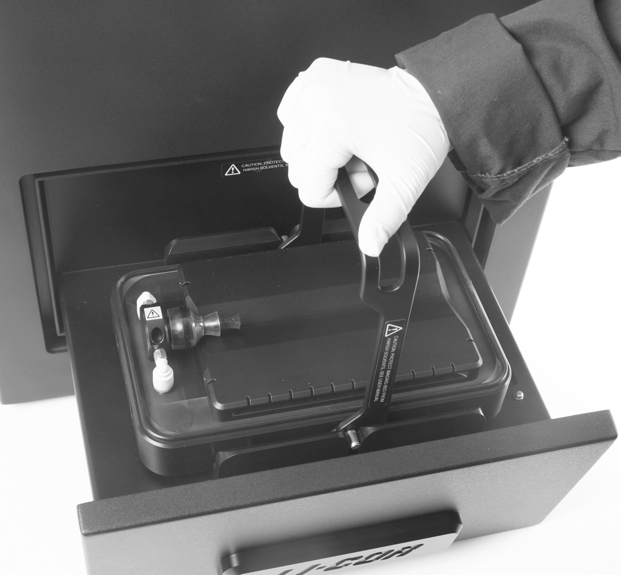
- Move the imaging bed handle to its vertical position (Figure 106).
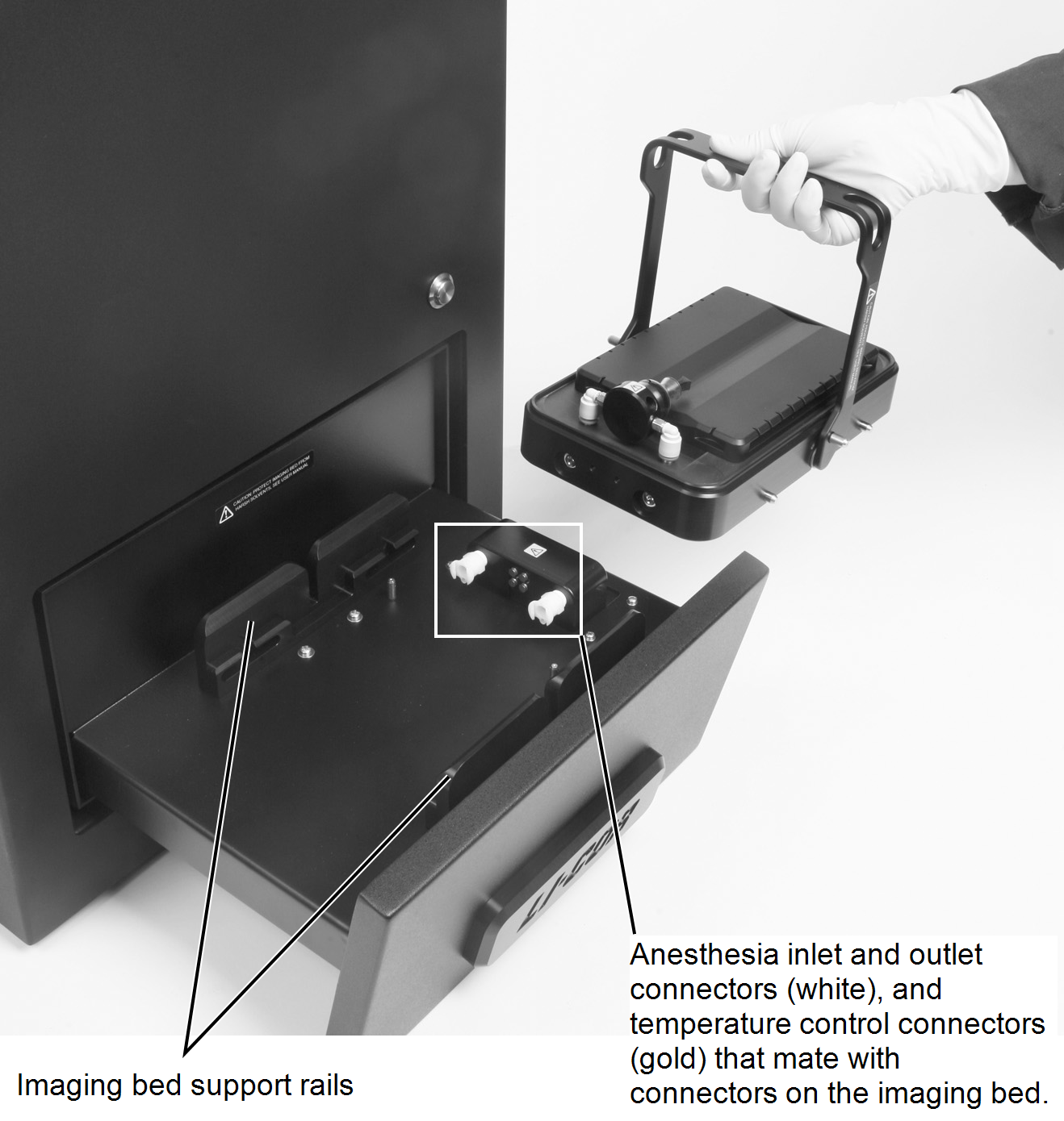
Figure 106. Imaging bed with handle in the vertical position and ready to insert in the imaging drawer.
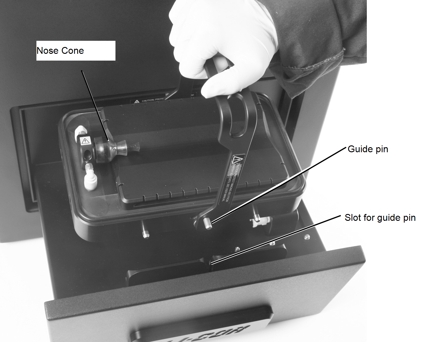
- Align the imaging bed guide pins with the slots in the support rails (Figure 107) of the imaging drawer and lower the imaging bed into the imaging drawer.
Imaging bed lowered onto the imaging drawer but not locked in place.
- Rotate the imaging bed handle from the vertical position down to the horizontal position, parallel to the bottom of the imaging drawer (Figure 108). Be careful not to pinch your fingers as the handle rotates downward.
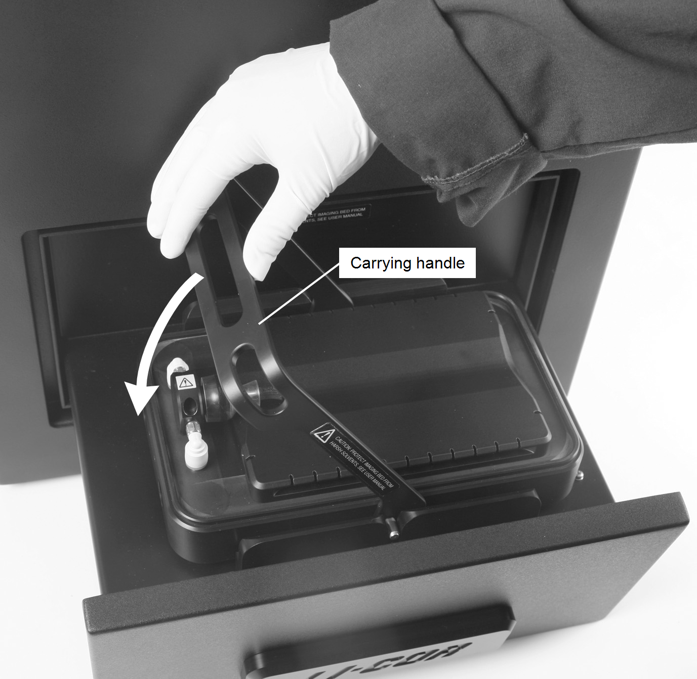
Imaging bed slides to the right when the handle is lowered and connects with the anesthesia gas ports and temperature control connectors in the imaging drawer.
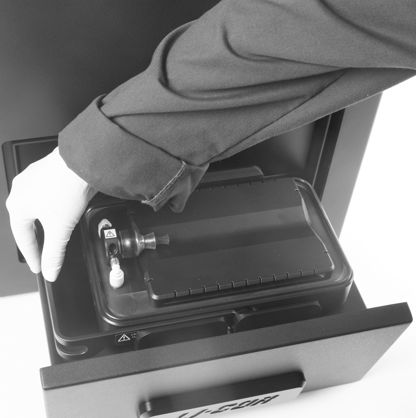
Imaging bed locks in place when the carrying handle is in the horizontal position.
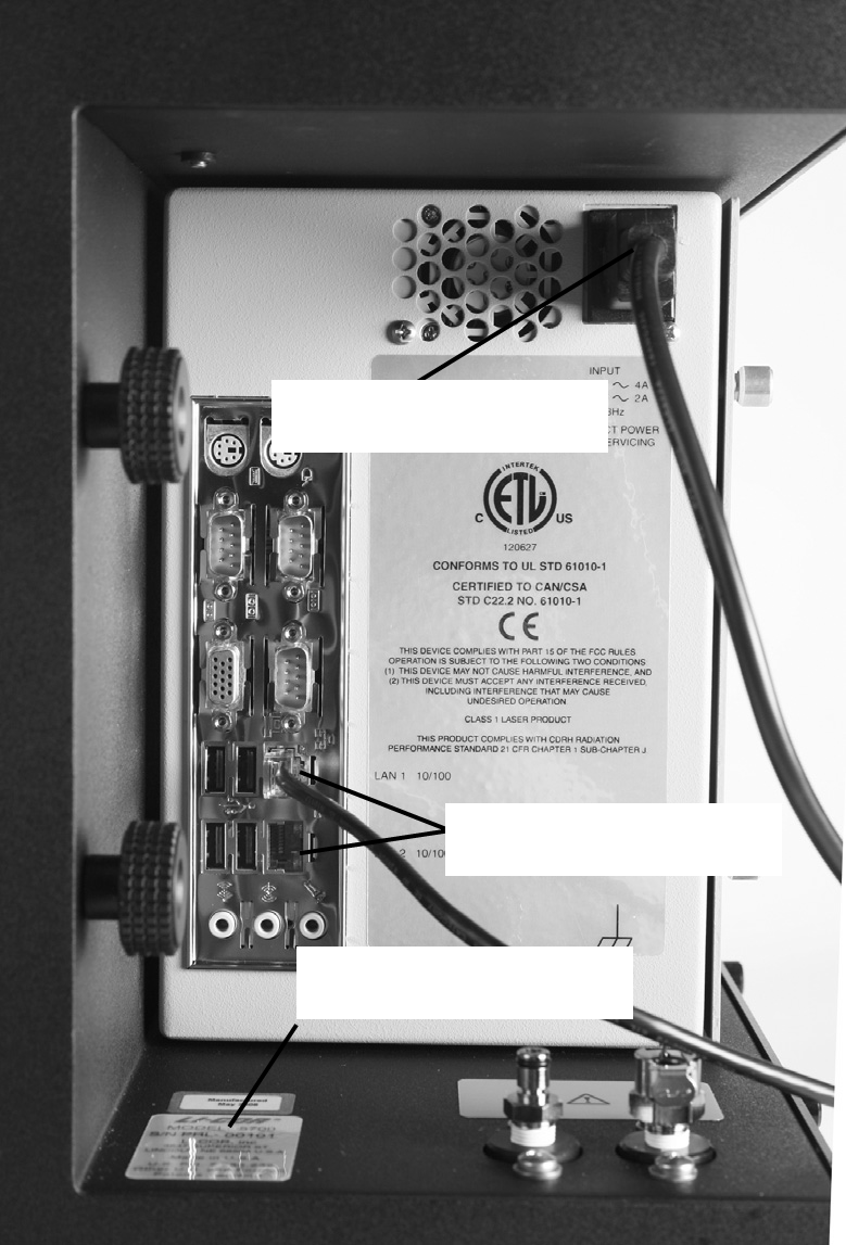
Computer Connections and Networking
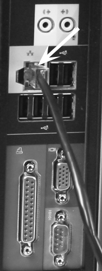
The computer supplied with the Pearl® Imaging System has two Ethernet ports. During installation, the port labeled LAN1 on the Pearl Imaging System control module (Figure 101. ) must be connected to one of the Ethernet ports on the computer. On instruments with a serial number below 3100, the Pearl Imaging System must be connected to the Ethernet port that is directly connected to the computer's motherboard (see Figure 109).
Note: Use only the supplied Cat. 5e RJ45 Ethernet cable to connect the Pearl Imaging System and computer.
When Image Studio™ Software starts, it searches for and discovers any Pearl Imagers on the network. If only one instrument is found, Image Studio Software establishes communication. If more than one instrument is found, you will be presented with a list of instruments and asked which to use.
Image Studio™ Software Features
Image acquisition with the Pearl Imaging System is designed to be as easy as possible. Typical imaging operations, such as choosing filters, exposure settings, or imaging algorithms, are eliminated by Image Studio software. The software also delivers properly exposed images on the first attempt, without saturated or underexposed pixels. This simplification of the imaging procedure enables additional capabilities such as “one-button” image acquisition, in which images are automatically acquired each time the Pearl Imaging System imaging drawer is closed. Capture of a time series of images is also possible.
Acquired images can be displayed singly, or side-by-side with other images for comparison. A movie can be created to sequentially play a set of images to more clearly visualize changes. Image Studio Software can be used to normalize acquisitions so that the same intensity value is displayed with the same color or grayscale value on all normalized images.
Regions of interest can be analyzed by using standard shape tools to identify both a background region and the region of interest. In addition, an Auto Shape tool automatically marks regions of interest and also provides a standard to which data can be normalized.
After analysis, images can be cropped, printed, or exported in a variety of ways. The data are also available for export and further analysis.
Optical System Description
Before image acquisition can be started, the imaging
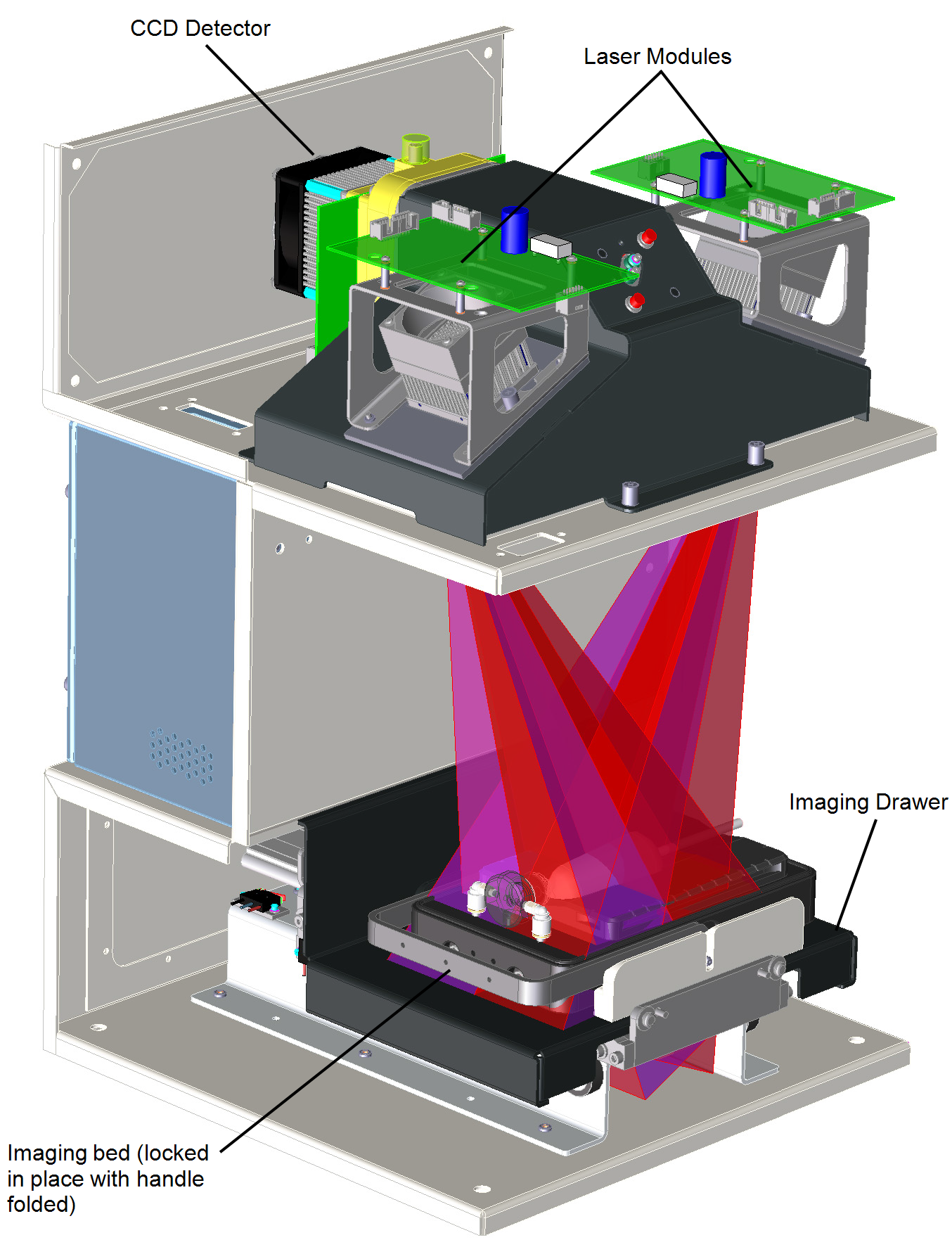
For fluorescent imaging, the Pearl Imaging System has two laser modules that work in tandem to illuminate the imaging
During image acquisition, similar sources from each laser module are turned on simultaneously, followed by image acquisition by the CCD detector. As each pair of similar sources are turned on and off, the CCD acquires all three images in less than 30 seconds. A single image acquisition consists of images for two fluorescent probes in the 700 and 800 nm channels, plus a white light image (assuming all channels are enabled).
The quality of images from the Pearl® Imaging System is enhanced by a patented filtering system that dramatically reduces noise before detection by the CCD detector. Signal detection has also been optimized for LI‑COR® IRDye® near-infrared dyes, which eliminates the need for filter selection by the user before imaging. The unique imaging methodology used in the Pearl Imager acquires images without saturated or underexposed pixels on the first attempt with no user adjustments.
Six logs (22 bits) of dynamic range are available for each image.
Near-Infrared Detection
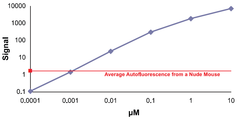
The Pearl Imaging System offers in vivo imaging in the near-infrared (NIR) where tissue autofluorescence and light scattering are low (Figure 112). Because of the lower tissue absorption coefficient in the NIR region (700-900 nm), light can penetrate to depths of several centimeters.
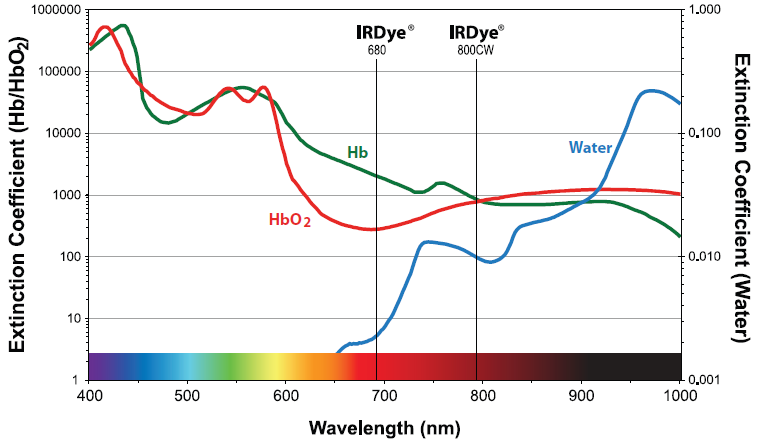
By contrast, tissue penetration depths are only a few millimeters in the visible region of the spectrum where autofluorescence and light scattering are comparatively high. Above 900 nm, water absorption can interfere with signal-to-background ratio. LI‑COR® IRDye® 680RD and IRDye 800CW (particularly IRDye 800CW) are not hindered by interfering autofluorescence and yield high signal-to-background, making them ideally suited for optical imaging in small animals. A review of the development of fluorochrome-labeled optical agents (Kovar, Simpson, Schutz-Geschwender, and Olive, 2007) is included with this manual.
Bioluminescent Detection
The Pearl Imaging System may be used with traditional bioluminescent cell lines and mouse models (in countries where certain patents are not applicable). The Pearl Imaging System provides excellent, low noise results from bioluminescence and will not produce image saturation.
Overview of Infrared In Vivo Imaging
With fluorescence based in vivo imaging projects, development of a targeted tracking agent begins much earlier than the actual animal imaging. Figure 113 illustrates the stages of development for a targeted tracking agent.
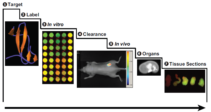
Each of the development stages in Figure 113 are discussed in greater detail below.
Target: in vivo imaging projects typically begin with identification of a potential targeted tracking agent, or probe, such as a ligand to a receptor or an antibody specific for use with a particular model system be it cancer or a disease process.
Label/Conjugation: Once a probe has been identified, then the task becomes labeling. Does the compound lend itself to conjugation with IRDye 800CW infrared dye for imaging? If the compound is a peptide or antibody containing lysines then amines are candidates for binding with the NHS ester form of the dye. Protein labeling kits are available that use the IRDye 800CW or IRDye 680RD NHS ester to label probes. Visit licor.com/brightsite for the latest list of labeled agents and corresponding part numbers.
In vitro Assays: Before starting a costly and time consuming in vivo experiment, probe specificity should be determined in vitro using the LI‑COR® Odyssey® CLx Imager, Odyssey Classic, or Odyssey Sa imaging system to perform cost-effective on-cell Western (OCW) or In-Cell Western™ (ICW) assays. Both are immunofluorescent-based assays performed in microplate format. The OCW allows monolayers of live cells to be screened with fluorescently-labeled targeted optical agents which are then fixed and stained for ratiometric analysis. The ICW uses targeted-specific primary antibodies and infrared-labeled secondary antibodies to detect target proteins in fixed cells.
The more data collected in vitro to confirm the targeting agent is responding as expected, the more confident you will be when starting an animal study. What kinds of tests should be done? Binding and specificity assays are key. These will help determine if the labeled targeting agent is binding specifically to the receptor of choice.
Clearance Studies: With the knowledge that the labeled targeting agent is binding specifically, in vivo clearance studies can proceed. After confirming specificity and binding in the homogenous cell environment with the OCW or ICW, the labeled targeting agent is evaluated in “tumor-negative” and “tumor-positive” animals to determine whether any of the multiple biological systems in the body alter or affect the actions of the labeled targeting agent. Clearance studies address important questions such as: 1) Does the probe collect beyond the intended target (e.g. liver, kidneys, or bladder)? 2) How long does it take for the targeting agent to clear the animal? 3) What is the ideal probe concentration? and 4) When is the best time post-injection to image in order to achieve the best signal-to-noise ratio?
in vivo Studies: Now a researcher can begin using the IRDye® 800CW targeting agents in their research projects with greater confidence. A typical experiment would include a negative control and a control of IRDye 800CW Carboxylate for dye-only effects, and the IRDye 800CW targeting agent. A repeat of the competition assay in vivo would be beneficial in confirming probe specificity in the animal and to identify possible complications. However, certain probes will not lend themselves to these types of studies.
Organs: More focused studies can be made of the targeting agent's localization by excising target organ(s) and imaging them on the Pearl Imager to visualize deposition of the labeled targeting agent in the organs.
Tissue Sections: To determine exact tissue localization of the biomarker, frozen, or paraffin embedded tissue sections can be scanned on a LI‑COR® Odyssey® Imaging System at a higher resolution.
References
Pearl Docking Station
Description

The Pearl Docking Station is an optional, external accessory that duplicates many of the features of the
- Duplicates the docking hardware in the Pearl Imager imaging drawer, allowing an accessory imaging bed to be locked in place on the docking station similar to the Pearl imaging drawer.
- Provides temperature and anesthesia gas control to a Pearl accessory imaging bed outside of the Pearl Imager, allowing animals to be prepared for imaging at an external station.
- Warms the heater plate in any of the Pearl accessory imaging beds (when docked) to 38 °C so animals can be placed on warm imaging beds before transfer to the Pearl Imager.
- Provides a rotameter, isoflurane scrubber, and anesthesia gas flow system similar to the Pearl Imager when an accessory imaging bed is locked in place on the docking station.
This chapter provides information on assembly and operation of the Pearl Docking Station only. The remaining chapters provide specific operational details on each of the accessory imaging beds. Information on the standard Pearl Imaging Bed is not provided in this manual since it can be found in the Pearl Imager Operator's Manual.
Assembling the Pearl Docking Station
WARNING: Isoflurane gas can leak in the amount supplied to the Pearl Imaging System Docking Station if the product is not used properly. Carefully follow the instructions in this chapter to ensure that the scavenging charcoal filter and user-supplied anesthesia system are properly connected, and that the nose cone on the imaging bed has a nose cone plug inserted when not in use.
AVERTISSEMENT:
L'anesthésie d'isoflurane peut fuir dans la quantité fournie à la station d'amarrage de Pearl si le produit n'est pas employé correctement. Suivez soigneusement les instructions dans ce chapitre pour vous assurer que le port d'échappement est relié à un filtre à charbon, que le système d'anesthésie fourni par l'utilisateur est correctement relié, et que le cone de nez est équipé d'un bouchon inséré.
- Unpack the Pearl® Imaging System Docking Station and any other accessory imaging beds, such as the Pearl Clean Box, so all parts are available for assembly.
Loosen the thumb nuts on the back of the rotameter stand. Orient the rotameter with tubing to the back of the stand as shown below. Connect the rotameter to the rotameter stand by sliding the rotameter over the mounting studs (similar to the Pearl Imaging System instrument) and tightening the thumb nuts.
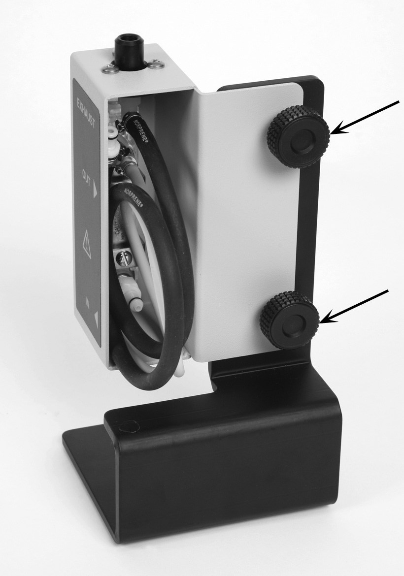
Figure 115. Docking station rotameter connects to the stand via two thumb nuts with the rotameter oriented to the front of the stand. - Connect the tube from the port labeled “OUT” on the rotameter to the port labeled “IN” on the back of the docking station. The gender of the connector prevents connection to the wrong port.
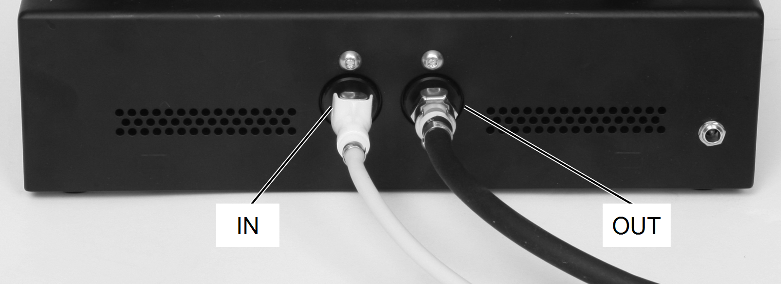
Figure 116. Docking station back panel. - Connect the tube from the port labeled “EXHAUST” on the rotameter to the port labeled “OUT” on the back of the docking station.
If using the Pearl Clean Box, connect one of the provided HEPA filter assemblies (packaged with the Clean Box) to the port labeled “IN” on the rotameter. The gender of the connector assures the filter will be plugged-in in the correct orientation.
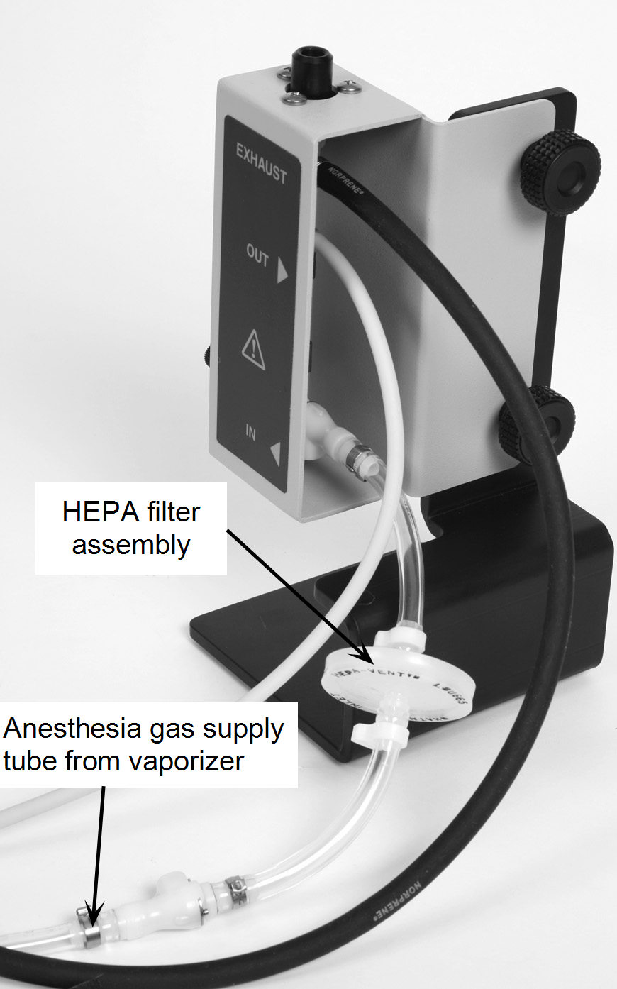
Figure 117. Docking station rotameter with HEPA filter assembly installed between the IN port on the rotameter and the anesthesia gas supply tube from the vaporizer. - Connect one of the provided HEPA filter assemblies between the SmartFlow system and the Induction Chamber.
- Connect the opposite end of the HEPA filter assembly to the provided anesthesia gas supply tube and then connect the other end of the anesthesia gas supply tube to one of the output manifold connectors on the SmartFlow Anesthesia System, or equivalent (Figure 118).
- Note: For imaging beds not requiring a HEPA filter, connect the anesthesia gas supply tube directly to the rotameter. For other vaporizers, it may be necessary to remove the connector that connects to the SmartFlow System and replace it with an appropriate fitting.
CAUTION: The Pearl® Imaging System Docking Station is compatible only with anesthesia systems that supply isoflurane gas. The flow rate and pressure into the instrument should not exceed 1 liter per minute and 1 psi, respectively. If the pressure exceeds 5 psi, the rotameter will not accurately show the flow to the nose cone.
ATTENTION:
La station d'amarrage de Pearl n'est compatible qu'avec les systèmes d'anesthésie qui fournissent le gaz isoflurane. Le débit et la pression dans l'instrument ne devraient pas excéder 1 litre par minute et 6.9 kPa, respectivement. Si la pression excède l'estimation de 34.5 kPa, le rotamètre ne montrera pas en juste proportion l'écoulement au cône de nez.

Hold the base of the rotameter stand and press the charcoal filter down onto the port labeled “EXHAUST” on the exterior of the rotameter. Alternatively, connect a user-supplied charcoal filter assembly to the EXHAUST port. Recommendations for monitoring and replacement of the charcoal filter are given in
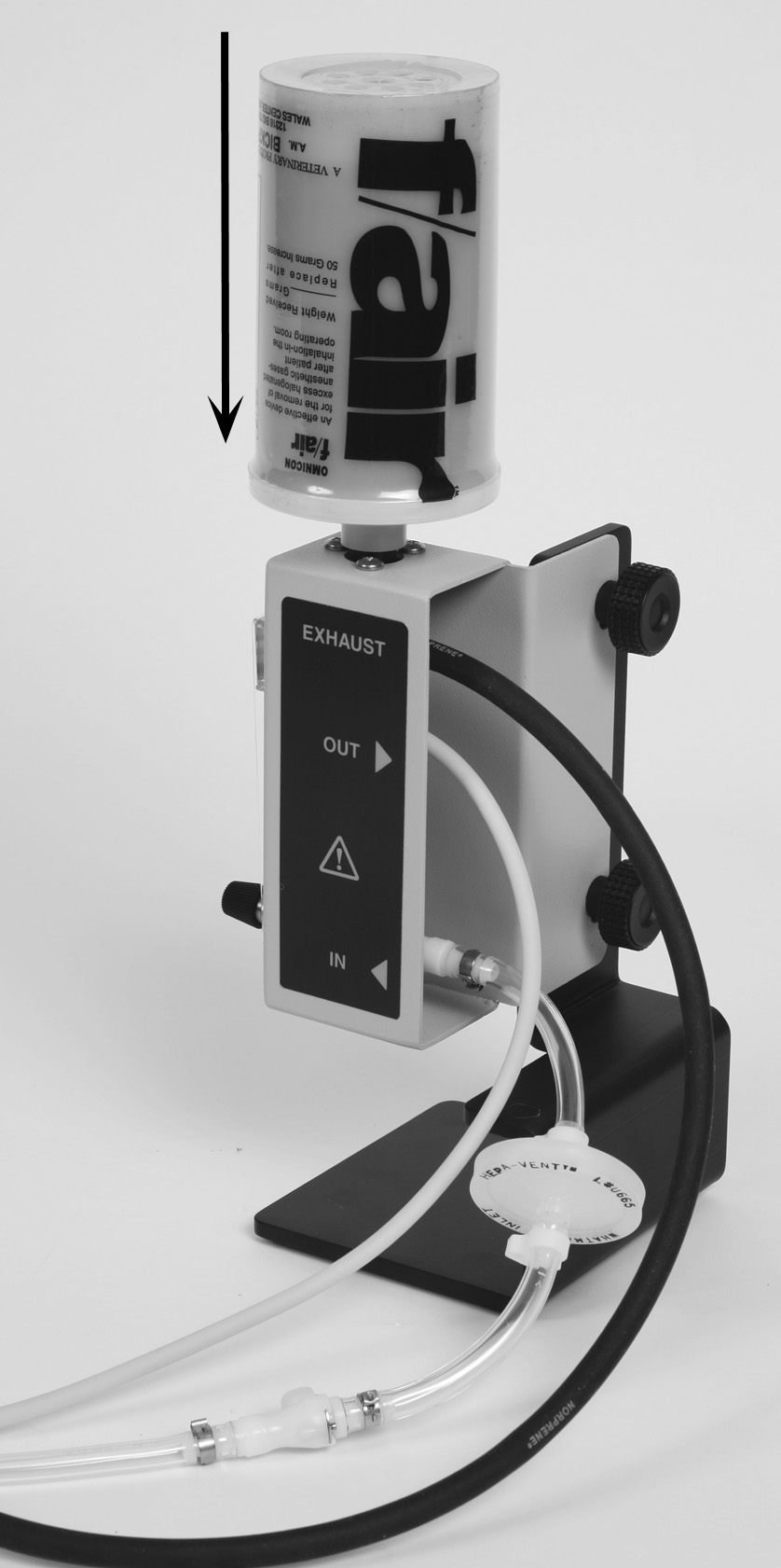
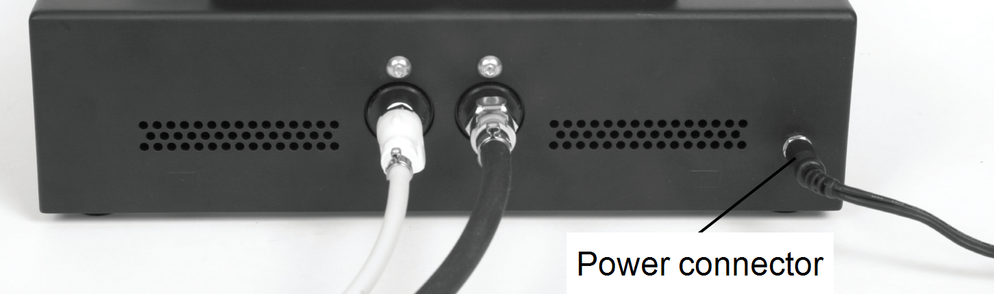
Figure 119. The included charcoal filter or a user supplied charcoal filter presses onto the external output port on the docking station rotameter. - Connect the power supply to a wall outlet and then to the back of the Pearl Docking Station.
Docking Station Operation
- Install a nose cone plug in the nose cone of the accessory imaging bed (Figure 121) and install the imaging bed on the Pearl® Imaging System Docking Station. Lock the imaging bed in place using the guide pins and locking handle as described in Chapter 2. Consult the appropriate chapter in this manual for any additional instructions for the specific imaging bed you are using.
WARNING: Make sure a black nose cone plug is tightly inserted in the nose cone before turning on the anesthesia gas. Failure to insert a nose cone plug will result in the release of isoflurane gas.
AVERTISSEMENT:
Assurez-vous qu'un bouchon noir pour cone de nez est bien inséré dans chacun des cones de nez avant de brancher le gaz anesthésiant. L'absence de bouchon peut provoquer une décharge de gas.
- Press the power button on the docking station front panel (Figure 122).
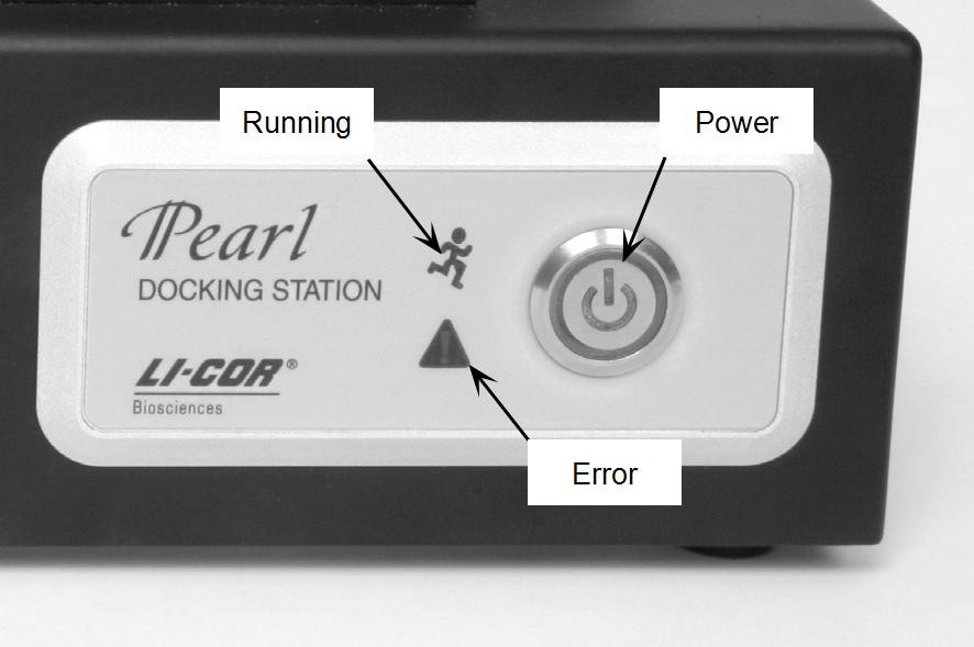
| Indicator | Description |
(Blue) | ON continuously when the docking station is powered on. OFF when an error condition exists or the power supply is disconnected. | |
(Green) | Blinks rapidly when heater plate is not within 1.5 °C of the 38 °C set point. | |
ON continuously when heater plate is within 1.5 °C of the 38 °C set point. | ||
OFF when an imaging bed is not installed on the docking station or there is an error condition. | ||
(Red) | ON continuously when the heater plate temperature is greater than 5 °C above set point (38 °C). The heater plate is automatically turned OFF, but the indicator remains on. Disconnect the power supply to turn off the red warning light and reset the temperature controller. Connect the power supply again after the heater plate has cooled. | |
Blinks slowly when the current to the heater plate is not correct. This may indicate that the heater plate contact pins are dirty, shorted (bent), or need replacement. See Chapter 5 of the Pearl Imager Operator's Manual for the contact pin replacement procedure. |
- Wait for the heater plate to reach the set point (38 °C). The green “running” icon blinks rapidly until the set point is reached and then stops blinking and remains on (Figure 122).
- Use the adjustment knob on the rotameter to set the flow rate to 0.5 liters per minute (typical) and start gas flow from isoflurane vaporizer or equivalent. Allow 1 minute to prime the system with isoflurane gas. Observe the safety warnings given in Chapter 1 concerning use of isoflurane gas and oxygen. Follow the instructions from the manufacturer of the anesthesia system to anesthetize mice.
CAUTION: To prevent pressure build up in the external anesthesia system, don’t close the rotameter on the Pearl Docking Station unless the anesthesia system is properly vented.
AVERTISSEMENT:
Pour empêcher l'accumulation de pression dans le système externe d'anesthésie, ne fermez pas le rotamètre sur la station d'amarrage de Pearl à moins que le système d'anesthésie soit correctement aéré.
- Move the mouse from the induction chamber to the imaging bed, remove the nose cone plug, and slide the muzzle of the mouse into the nose cone. Complete instructions can be found in Chapter 4
- Lift the locking handle on the accessory imaging bed and remove it from the docking station. Move the imaging bed immediately to the Pearl Imager for imaging.
- Important: The flow of anesthesia gas stops after the imaging bed is unlocked from the docking station and does not start again until the imaging bed is locked into the Pearl Imager imaging drawer or returned to the docking station and locked in place.
- After imaging, remove the accessory imaging bed, lock it back on the docking station, remove the mouse to a recovery chamber, and re-insert the nose cone plug to stop the flow of anesthesia gas. Turn off the flow of anesthesia gas after imaging the last mouse.
Routine Maintenance
The Pearl Docking Station requires only minimal maintenance. Disconnect power before servicing. Clean the exterior case parts with cloth dampened with warm water. Do not submerge or power wash. Inspect all cables and power cords for evidence of fraying, exposed wire, or loose connections. Periodically inspect external tubing for cracking or damage that could cause leaks.
Docking Station Specifications
Docking Station Operating Conditions: For Indoor use only; operating temperature 15-35 °C, dew point not greater than 20 °C, non-condensing. Storage temperature of -20 to 60 °C.
Power Requirements: 100-240 VAC; 47-63 Hz; 1 A at 100 VAC.
Power Input Connector: 5.5 × 2.5 mm, center positive.
External Power Supply Input connector: 3 Pin IEC 320 input receptacle.
Temperature Setting: 38 °C ± 1 °C.
Docking Station Dimensions: 5.0" H × 11.3" W × 9.3" D (12.7 × 28.7 × 23.6 cm).
Docking Station Weight: 5.5 lbs (2.5 kg).
Rotameter Dimensions: 10.3" H × 5.0" W × 6.3" D (26.1 × 12.7 × 16 cm). Height with charcoal filter is 16.5" (41.9 cm).
Rotameter Weight: 2.2 lbs (1.0 kg).