System Overview
External Panels and Controls
Front Panel and Scan Surface

Power Button
Briefly press the Power button to turn the imager on and off when the imager is not connected to LI‑COR® Acquisition Software.
When the imager is powered on, the power button will be illuminated solid blue.
During the process of powering on or powering off, the power button will flash blue.
Display Panel
The front display panel shows the following:
- The username chosen in LI‑COR® Acquisition Software when the Odyssey M Imager was connected to LI‑COR Acquisition Software.
- If the lid is open.
- The time remaining in a scan.
- During a scan, the type of scan will be shown.
Front Panel Indicator Light
An indicator light is located on the front panel. In most circumstances, the color of the light mirrors a status indicated in LI‑COR Acquisition Software.
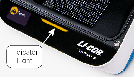
| Indicator Light State | Meaning |
| Off | No connection to LI‑COR Acquisition Software |
| Green | Ready or Done |
| Yellow/Orange | Scanning or Lid Open |
| Red | And error has occurred. Check LI‑COR Acquisition Software for more information. |
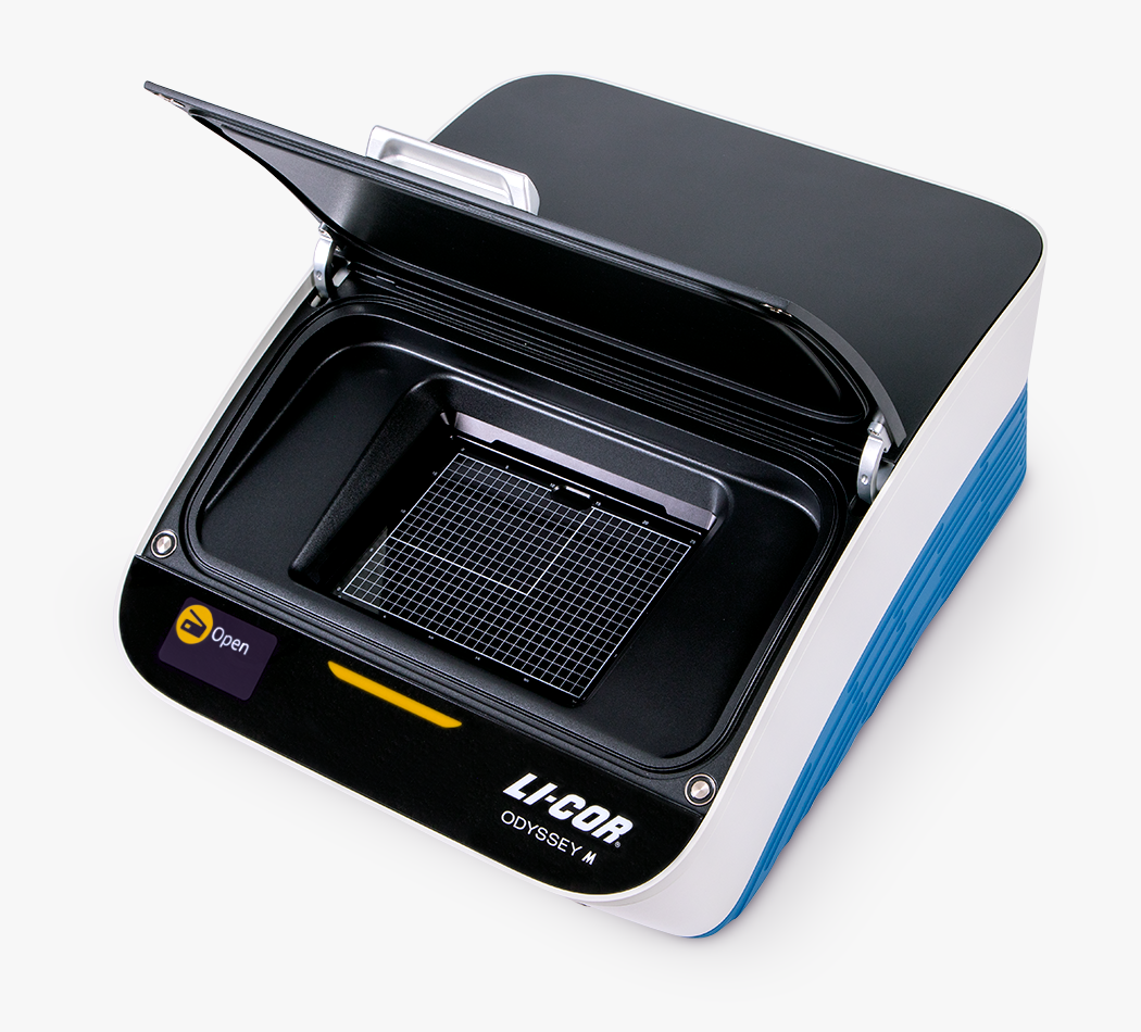
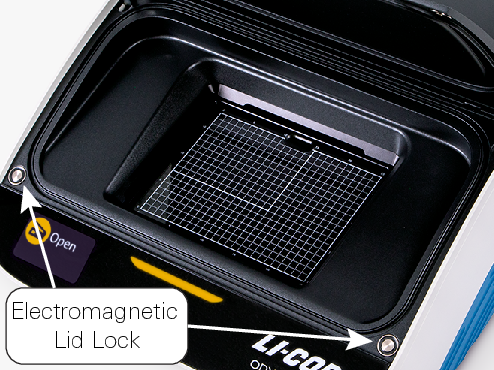
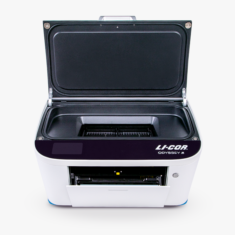
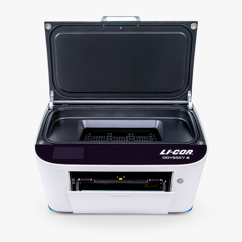
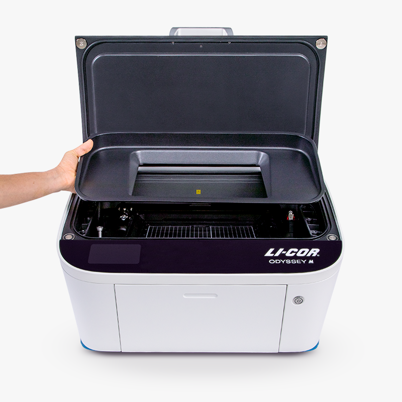
Scan Surface
Gently lift the handle on the front edge of the lid to access the Scan Surface. Instructions for acquiring images are provided in Operation.
Gently press down on the lid when you are ready to close it. There will be slight upward resistance when the lid is nearly in the close position to help prevent the lid from closing with excessive force.
During imaging, the Scan Surface will automatically move to the rear portion of the imager to place the samples in the appropriate location relative to components of the optical system. When the scan is complete, the Scan Surface will return to the front of the imager.
Scan Surface Position
The correct Scan Surface position is shown in Figure 13, and an incorrect Scan Surface position is shown in Figure 14.
Caution: If the Scan Surface warning label is visible or you otherwise notice that the Scan Surface is not correctly positioned, do not place a sample on the Scan Surface. Do not use the Odyssey M until the problem is addressed and the Scan Surface is positioned correctly. Trying to perform a scan while the Scan Surface is not correctly positioned can cause damage to the Odyssey M.

Addressing a Scan Surface Position Problem
If you notice that the Scan Surface is not positioned correctly, the following steps are a good procedure to start with to try to solve the problem.
Ensure that there are no loose objects on or around the Scan Surface.
Close the Rear Lid and Front Lid. It is best to also have the door to the Tray Holder closed.
Press the Power button on the front panel to power off the Odyssey M.
Press the Power button to power on the Odyssey M.
Contact LI‑COR Support if this procedure does not solve the problem or if you have questions.
Move Scan Surface
Use the following instructions to move the Scan Surface to the rear of the imager. You may need to do this, for example, to clean the grid pattern below the Scan Surface (see Clean the Grid Below the Scan Surface).
Press the Power button to power on the imager.
Wait for the Power button to become solid blue before continuing.
Open the front lid.
Briefly press the Power button .
Close the front lid within 5 seconds while the Power button is still flashing.
If you close the front lid within 5 seconds, the Scan Surface will move to a position in the rear portion of the imager.
While the Scan Surface is moving, the Power button will continue to flash blue and the lid will remain locked. Once in position, the Power button light will turn off and the lid will unlock.
If you leave the front lid open for longer than 5 seconds, the imager will power down without moving the Scan Surface.
Manually Move Scan Surface
If there is a power outage during a scan, the Scan Surface will not move forward normally. If the Scan Surface is in the rear portion of the imager and is not moving forward normally, you may need to move the Scan Surface forward manually by following these steps.
Ensure power to the imager is disconnected (see Disconnecting the Power).
Open the front lid.
Pull upward on the Sample Enclosure to remove it.

Figure 16. With the Sample Enclosure removed, a thumb screw will be visible.
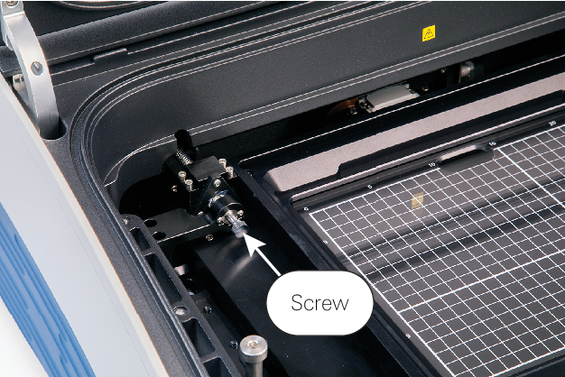
Figure 17. Rotate the thumb screw by hand clockwise to move the Scan Surface forward.
If the Scan Surface does not move, please contact LI‑COR Technical Support. Do not attempt to move the Scan Surface by applying force to it.
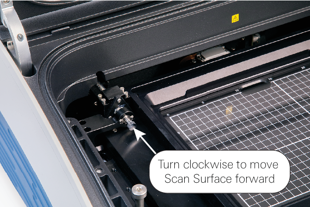
Figure 18.
Clean Front Panel
To clean the front panel, use mild soap and water. Do not allow soap or water to enter the imager.
Remove any debris from the electromagnets on the front two corners of the front lid.
Clean the Grid Below the Scan Surface
Cleaning the grid pattern beneath the Scan Surface is not part of regular maintenance. The grid does not need to be cleaned routinely. Over time, depending on lab conditions, the grid may need to be cleaned.
If the grid does need to be cleaned, first gain access to the grid by using the automated Scan Surface moving procedure (see Move Scan Surface) to move the Scan Surface to the rear of the imager.
If possible, use a microfiber cloth to gently wipe the grid clean.
If necessary, use mild soap and water.
Do not allow soap or water to enter the imager.
Do not allow soap to get on the greased bearings adjacent to the grid.
Clean Underside of Scan Surface
Cleaning the underside of the Scan Surface is not part of regular maintenance. The underside of the Scan Surface does not need to be cleaned routinely. Over time, depending on lab conditions, the underside may need to be cleaned. The following instructions show how the Scan Surface can be removed to clean the underside.
Gently open the front lid.
Remove the Sample Enclosure (see Sample Enclosure).
Loosen the three sets of screws on the frame of the Scan Surface using a 5/64" hex allen wrench. Ensure the screw, washer, spring, and ball are loosened on every set. The hardware is captive with the sample glass frame.
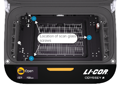
Figure 20. Pull the Scan Surface frame straight up. If it does not come up, ensure the screws are loosened.
Flip over the Scan Surface.
Do not remove the glass from the frame!
Thoroughly clean the glass Scan Surface with ultrapure water and wipe with a lint-free tissue.
Do not use scouring compounds or abrasive scouring pads. The glass can scratch, which can affect the scanned image.
Repeat the wash with 70% ethanol to remove any visible smears. Use methanol to remove any remaining residues.
Reinstall the Scan Surface by aligning balls on the glass frame with their sockets on the Y-stage and tighten screws (torque not to exceed 8 in-lbs).
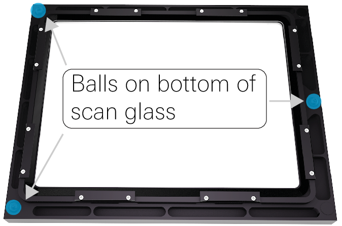
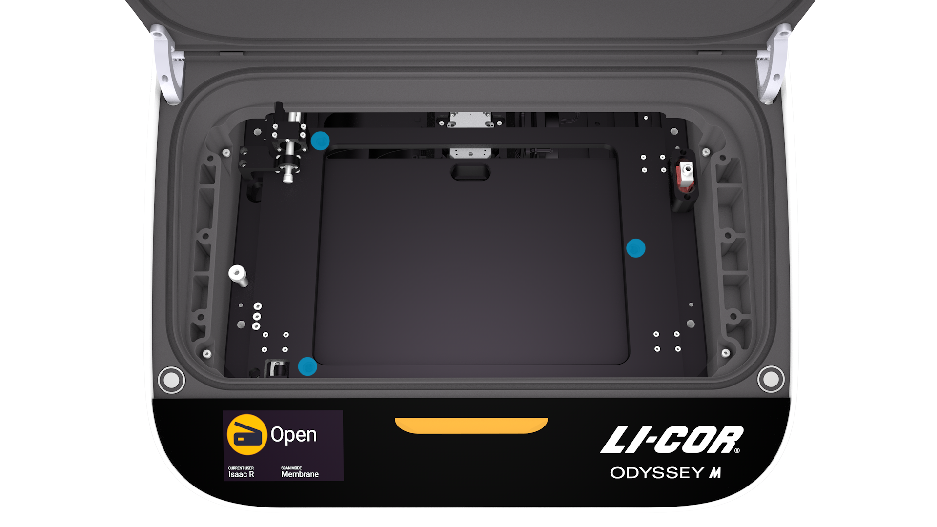
Figure 21. Balls on bottom of glass frame Figure 22. Y-Stage sockets
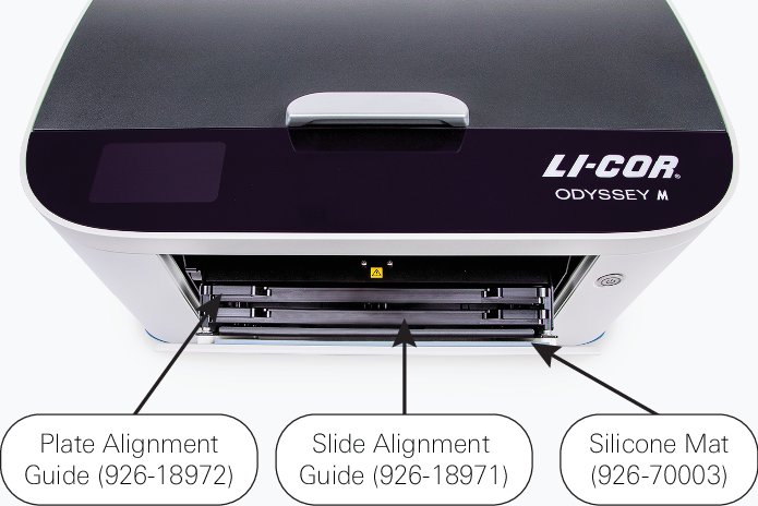
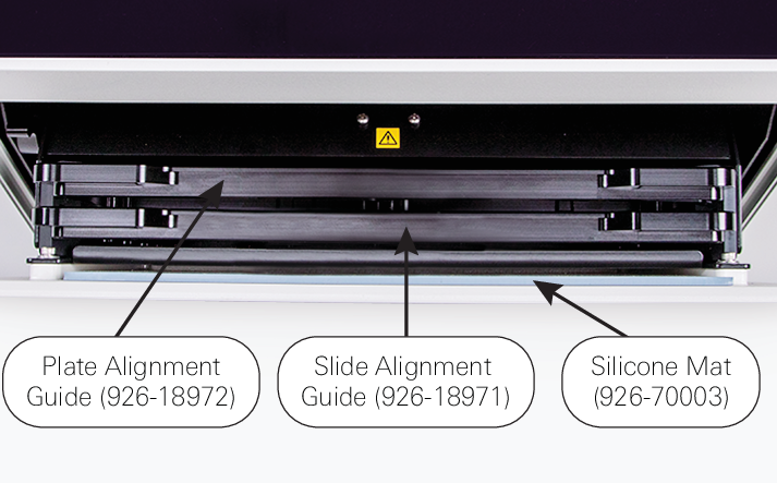
Alignment Guides
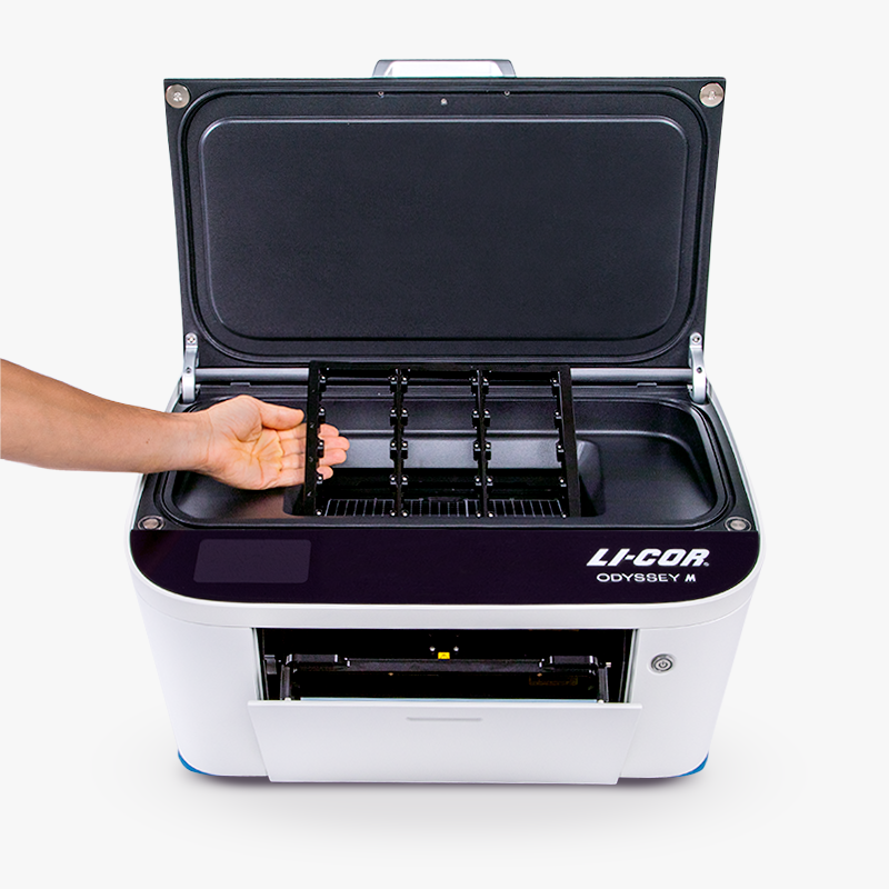
Plate Alignment Guide
Use the Plate Alignment Guide (926-18972) to precisely position multiwell plates during imaging. The Plate Alignment Guide is held in position by magnets.
 |  |
Use the (PN 926-18971) to precisely position microscope slides during imaging. The is held in position by magnets.
 |  |
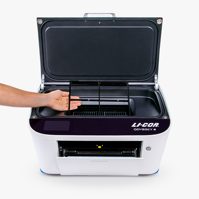
Sample Enclosure
The Sample Enclosure is the frame surrounding the Scan Surface. The Sample Enclosure is held in place by magnets and needs to be removed in some circumstances.
Remove the Sample Enclosure
Pull upward on the Sample Enclosure to remove it.
Installing the Sample Enclosure
Lower the Sample Enclosure into place. The magnets will attract and pull the Sample Enclosure into position.
Tray Holder
The Tray Holder is used to store the following accessories: the Plate Alignment Guide, the Slide Alignment Guide, and the Silicone Mat. These accessories fit in individual slots within the Tray Holder.
To open the Tray Holder, gently push the door of the Tray Holder, then release. The door will pivot open, allowing access to the accessories inside. Slide the accessories out of their slots when you need to use them, or slide them back into their slots to store them in the Tray Holder.
To close the Tray Holder, gently push the front of the door of the Tray Holder into the imager until it latches.
 |  |
Remove Tray Holder
The Tray Holder on the front of the imager can be removed for certain maintenance tasks, such as cleaning the fan filter (see Clean or Replace Fan Filter). For more information about the Tray Holder, see Tray Holder.
To remove the Tray Holder:
Gently push the door of the Tray Holder, then release. The door will pivot open.
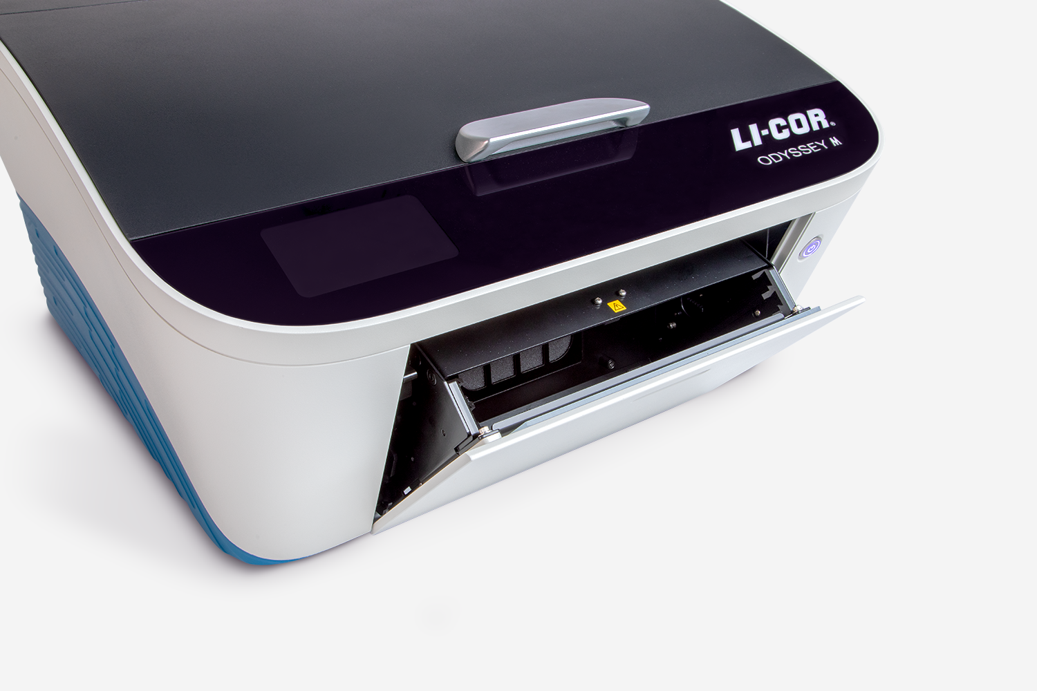
Figure 30. Remove everything inside the Tray Holder.
With the door open, push the front of the Tray Holder into the imager. It will move into the imager about 0.5 in.
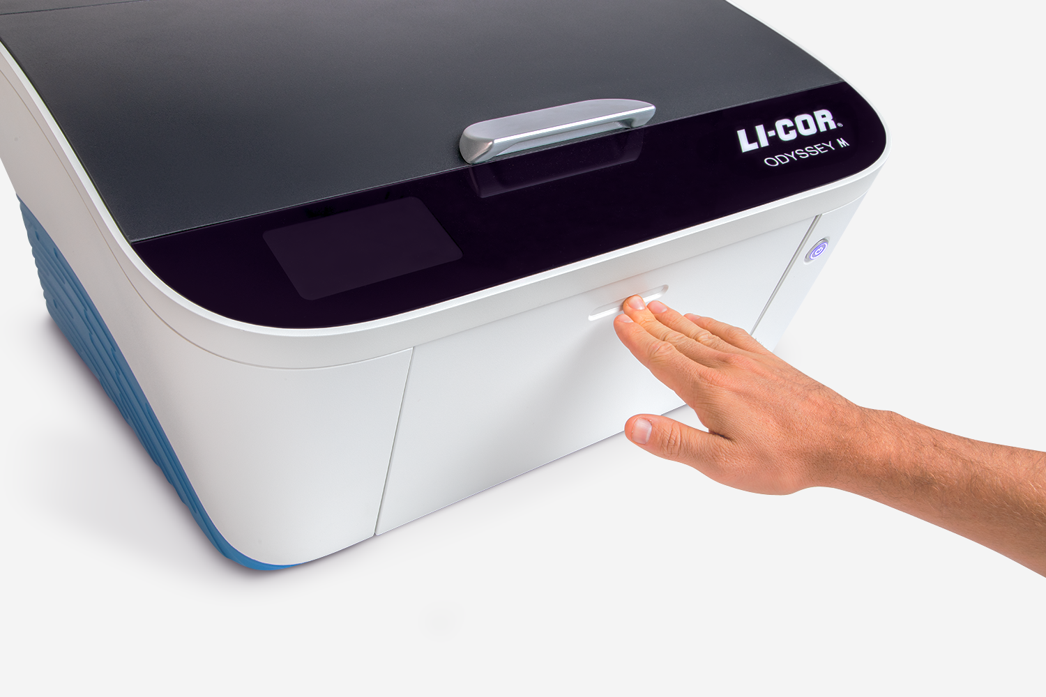
Figure 31. Push up the holding lever until it stops and hold the lever in that position.
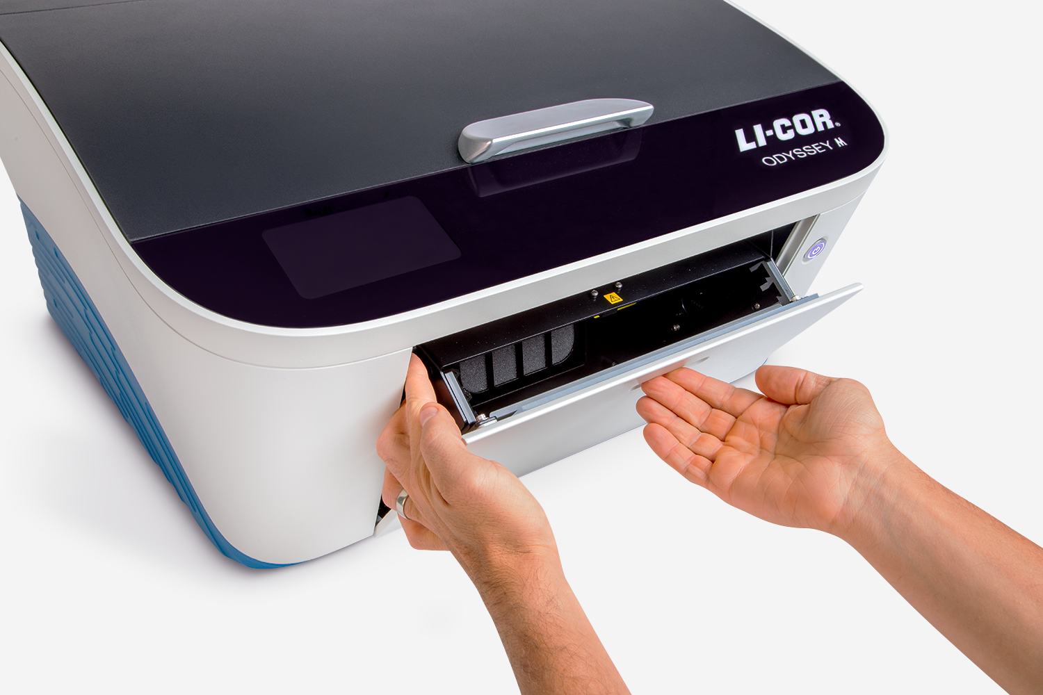
Figure 32. Support the Tray Holder with your hand while allowing it to rotate forward out of the imager.
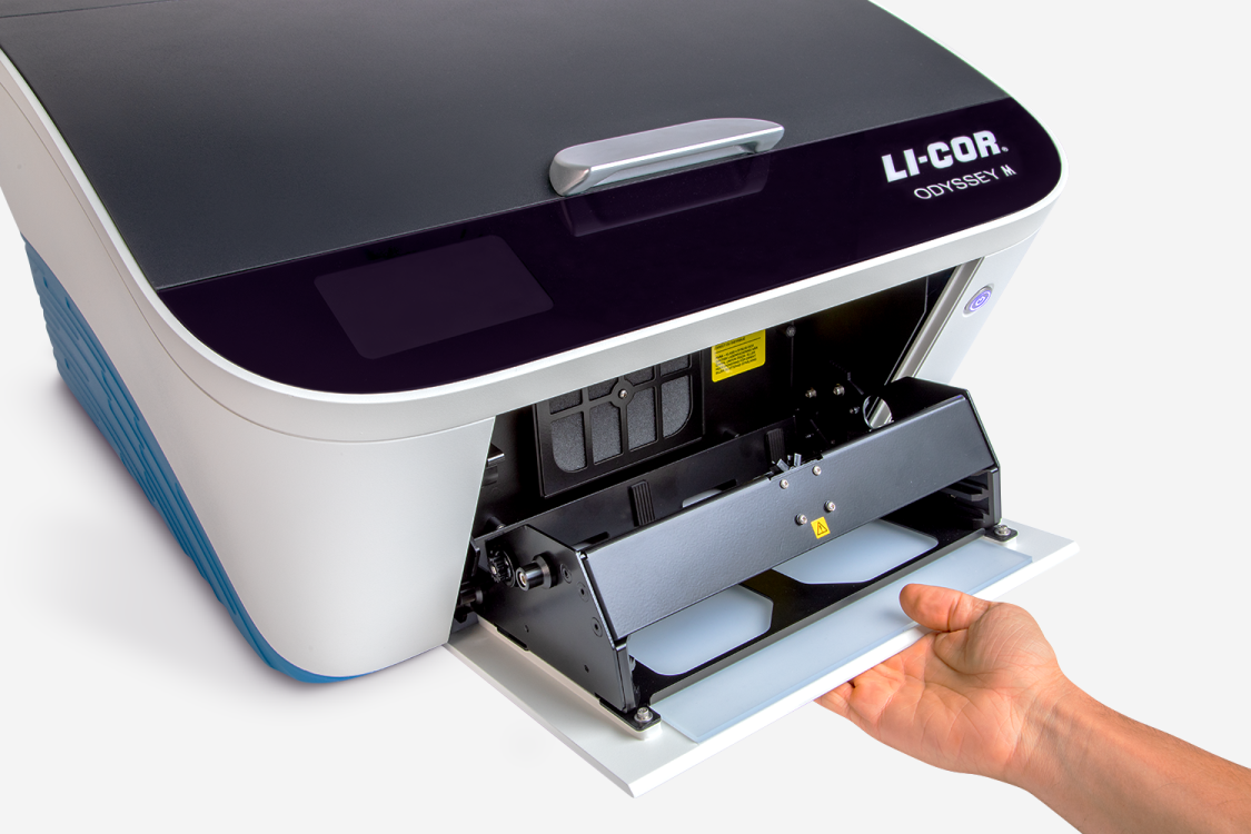
Figure 33. Pull the Tray Holder up and away from the base of the imager. The roller pins on the Tray Holder will detach from the hooks on the imager.
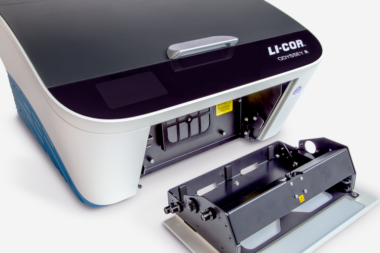
Figure 34.
Install Tray Holder
Position the lower roller pins on the left and right sides of the Tray Holder into their corresponding hooks.
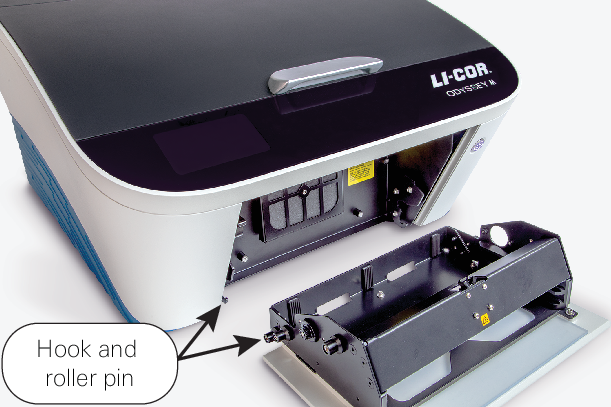
Figure 35. Rotate the Tray Holder to the closed position. The Stop Lever will reset itself when the Tray Holder is closed.
Figure 36.
Serial Number
The serial number for your Odyssey M is located inside the Tray Holder near the top. The serial number is in this format: ODM-XXXX (ODM- followed by four numbers).

Rear Panel
This is the Rear Panel of the Odyssey M Imager.
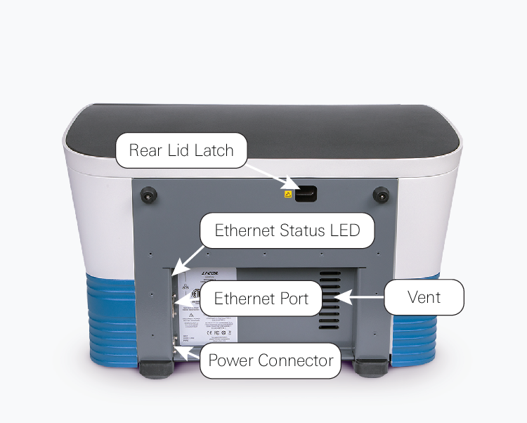
Rear Lid Latch Access Hole: A switch inside this hole allows you to unlatch the rear lid. Do not attempt to open the rear lid without reading instructions in the Rear Lid section Rear Lid carefully.
The rear lid is safety interlocked. Removing the lid removes power to the illumination sources and the motors.
- Ethernet Status: Two LED status indicators show if the Ethernet connection is transmitting or receiving information.
- Exhaust: The slotted openings help ventilate air through the imager.
- Power IN: Plug the DC power plug part of the LI‑COR provided power adapter into this port.
Rear Lid
The rear lid of the imager can be removed, if necessary, to retrieve samples (see Retrieve Samples) or to clean the chemi module (Chemi Module Glass).
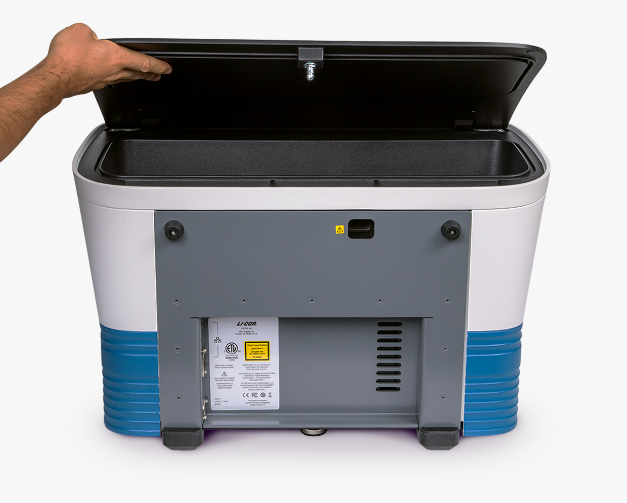
Remove Rear Lid
If you need to retrieve a sample or you need to clean the glass cover of the chemi imaging module, the rear lid can be removed using the following procedure.
The rear lid is safety interlocked. Removing the lid removes power to the illumination sources and the motors.
Exit LI‑COR® Acquisition Software
 .
.Turn off the Odyssey M by pressing the Power button on the front panel.
Disconnect the power cord. See Disconnecting the Power for more information about disconnecting power.
On the rear panel, locate the latch access hole.
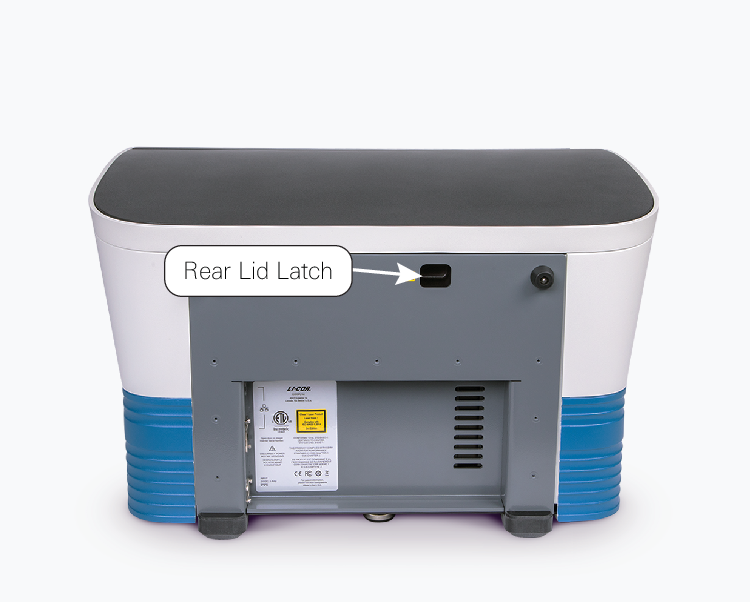
Figure 40. Inside the latch hole, press the switch to the left to release the latch. The rear lid will pop up slightly.
Lift the rear lid up slightly (about 10 - 20 degrees).
Grab the rear lid and gently slide it toward the rear of the imager. Pulling the rear lid slightly will allow the two connectors on the front side of the lid to be removed from their sockets, and the rear lid can then be separated from the imager and set aside.
You can then proceed with sample retrieval instructions (see Retrieve Samples) or instructions for cleaning the glass covering of the chemi module (see Chemi Module Glass).
To attach the rear lid back to the imager, slide the rear lid at a slight angle to the back of the imager to reengage the connectors. Press firmly down in the middle of the back edge to reengage the latch.
Retrieve Samples
As described in Scan Surface, the Scan Surface automatically moves to the optical system in the rear of the imager during a scan. If a power failure occurs during the scan when the Scan Surface is in the rear of the imager, the Scan Surface will not be able to return to the front area normally.
If the Scan Surface does not return to the front area normally and you need to access samples within the imager, first try to move the Scan Surface forward manually using the procedure in Manually Move Scan Surface. If the Scan Surface cannot be moved forward manually, follow instructions for removing the rear lid (see Remove Rear Lid).
With the lid removed, look for the samples. If there is a clear, unobstructed path that can be used to safely remove the samples without impacting internal components of the imager, then carefully remove the samples.
Chemi Module Glass
The Chemi Imaging Module (available on Odyssey M model 3350) has a glass covering. Do not attempt to clean this glass covering. If you believe the glass covering has become contaminated (for example, something has been spilled on it), contact LI‑COR Technical Support for assistance.
General Description of Scanning
Scans are initiated using LI‑COR® Acquisition Software.
LI‑COR Acquisition Software Overview
LI‑COR Acquisition Software provides step-by-step workflows for imaging the types of assays that the Odyssey M is intended to image. Choose the appropriate workflow for the type of assay that you want to image, then follow the guidance provided on the pages in the software imaging workflow.
Optical System Description
Brief Description of Illumination Sources
Laser
Lasers are narrow wavelength (e.g. 488nm ± 1nm), high intensity light. Lasers are used as an excitation source for substances that emit light at a specific wavelength after being excited by light at a specific wavelength. This process of light excitation and emission is known as fluorescence. Fluorescence detection can be used for samples or fluorophores. The benefit of using lasers to induce fluorescence is that specific structures (those excited by the wavelength of the incident laser) will be illuminated, but the rest of the sample that does not fluoresce under the indicent laser's wavelength will not be illuminated. Fluorescence enables accurate targeting and imaging. Fluorescence is the preferred method when accurate quantification of samples is required.
Examples
Fluorescent Western blots
In‑Cell Western™ Assay
Transillumination (Transmitted Light)
Transillumination involves transmitting visible light (or in some cases UV light) through your sample. The light is attenuated in the sample via absorption (which generates contrast) and the transmitted light is recorded. Transillumination creates even illumination of the sample to observe highly contrasted, stained, or naturally pigmented samples. The illumination wavelength (and emission filter) are selected based on the spectral characteristics of the sample to generate the best contrast. Images in the RGB (red, green, blue) format, also called "true color" images, are a composite of three independent grayscale images that correspond to the intensity of red, green, and blue light transmitted by the sample.
Examples
Coomassie or silver staining of protein gels
H&E stained tissue sections
Epi-Illumination (Reflected Light)
Method of choice for imaging samples that are not translucent or transparent. In epi-illumination, the recorded light is reflected from the sample with absorption and diffraction of the reflected light by the sample resulting in discernible variations in the image, from black through various shades of gray, or color if the sample is colored. Epi-illumination creates even illumination of the sample to observe highly contrasted, stained or naturally pigmented samples. For grayscale images the illumination wavelength (and emission filter) are selected based on the spectral characteristics of the sample to generate the best contrast. Images in the RGB (red, green, blue) format, also called "true color" images, are a composite of three independent grayscale images that correspond to the intensity of red, green, and blue light transmitted by the sample.
Examples
Western blot membranes using colorimetric substrates or stains
Colorimetric MW markers used in chemiluminescent blots