Installation
Placement in the Laboratory
The Odyssey M Imager Model 3340 weighs 115 lbs (52 kg). The Odyssey M Imager Model 3350 weighs 121 lbs (55 kg). The imager should be placed on a laboratory bench that is level and sufficiently sturdy to bear the imager's weight. The bench should also be able to bear the weight of the computer if the computer will be installed beside the Odyssey M Imager.
The Odyssey M is intended for indoor use only.
Ambient Laboratory Conditions
Place the Odyssey M Imager away from external heat sources (furnaces, windows, etc.). Additional heating can cause high temperatures within the enclosure. Place the instrument away from sinks or other sources of water that pose a shock hazard. Recommended operating conditions are and a dew point not greater than to prevent condensation on the laser/microscope assembly during operation. Allow the instrument to adjust to the temperature and humidity of the room before powering it on to avoid damaging the instrument. It may be necessary to allow up to a day in the new location in cases of extreme temperature and/or humidity change.
Imager Ventilation
The instrument enclosure and circuit boards are cooled with multiple internal fans. The fan on the rear of the instrument serves as an exhaust port, so the fan shrouds are not filtered, and the cover serves only as an exhaust outlet. There are no restrictions regarding placement of the instrument as spacers on the rear of the instrument ensure sufficient airflow for the exhaust port. However, it is important to not allow any objects (e.g., paper or a cover) to block airflow from the exhaust port while the instrument is on.
Space Requirements
The Odyssey M Imager requires an area approximately 24" width × 30" depth × 15" height (61 cm width × 76 cm depth × 38 cm height). With the lid fully open, the Odyssey M has a height of 28" (71 cm).
Electrical Considerations
Power Cords
The Odyssey M is provided with a power supply that converts wall voltage to 24 V DC. Use only the provided power supply cord to connect the Odyssey M to the wall outlet.
The plug will only fit into a grounding-type outlet. This is a necessary safety feature. If you are unable to insert the plug into the outlet, you will need to replace the outlet. Do not defeat the purpose of the grounding-type plug.
Do not place the Odyssey M where the power cord will be walked on or exposed to water or chemical spills.
The Odyssey M draws < 3 Amps at 120V. If an extension cord is used, make sure the total of the ampere ratings on the instruments plugged into the extension cord does not exceed the extension cord ampere rating. Also make sure the total amperage of instruments plugged into the wall outlet does not exceed the amperage capacity for the outlet (usually 15 or 20 amperes in the United States).
If the power supply's DIN8 output connector (Figure 6) is handled improperly (such as if the pins are pressed against a screw on the imager chassis), the pins in the power supply's DIN8 output connector can short or spark.
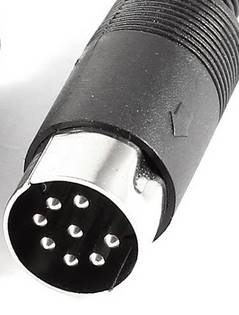
Figure 6. For information about disconnecting power, see Operation.
Fuse Information
There are no user-serviceable fuses. If the imager does not power on, please contact LICORbio or a LI‑COR representative.
Moving the Imager
LI‑COR recommends that you do not move your imager. Instead, please contact LI‑COR Technical Support for options.
LI‑COR cannot be held responsible for any damage incurred while moving, transporting, or shipping the
Leveling the Imager
Leveling the imager is important for many reasons, including to prevent liquid from pooling in the imaging tray and to keep the imager from tilting.
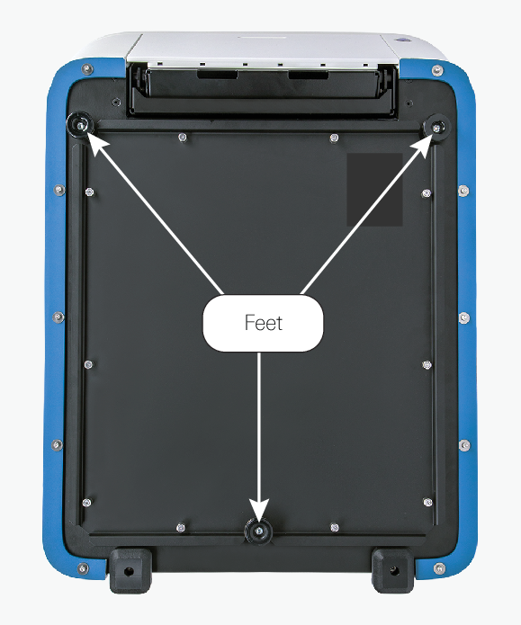
The imager sits on three feet. The two front feet can be used to raise or lower the front corners of the imager. The back foot cannot be adjusted.
Follow these steps to level the imager:
Place a circular bubble level on the center of the Scan Surface.
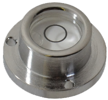
Figure 8. Use the bubble level to determine if the imager is level or which adjustments might be needed to level the imager.
Slightly raise the front of the imager to remove pressure from the foot you want to adjust.
Turn the screw on the foot clockwise to lower the corner or counterclockwise to raise the corner.
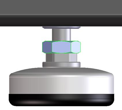
Figure 9. Turn the metal inserts on the feet to adjust the height.
Networking Cables

A Category 6 network cable is provided with the Odyssey M Imager. The networking port is on the back panel of the imager and is marked with the symbol in Figure 10.