System Overview
Optical System Description
Solid state diode lasers simultaneously provide light excitation at 685 nm, 785 nm, 488 nm, or 520 nm (two simultaneously). Collimating lenses, optical bandpass filters, and a focusing lens focus and tune the laser beams to produce an excitation spot on the scanning surface. The microscope electronics then modulate the laser beams to discriminate the signal fluorescence from background fluorescence. The scanner detection optics focus on the excitation spot and collect light from the fluorescing dyes.
The light is ultimately focused onto avalanche photodiodes that convert the light to an electrical signal for processing by the microscope detection electronics.
In the microscope electronics the signal is amplified, filtered, and finally converted to a digital value by an analog-to-digital converter. The digital signal is demodulated and coordinated with the microscope position to produce the image file.
The entire compact laser/microscope assembly travels on a platform that moves beneath the scanning surface along both the X- and Y-axes. It is adjustable in the Z-dimension to allow for focusing at the scan bed up to 5 mm above the scan bed to accommodate membranes, gels, microplates, and slides.
External Panels and Controls
Front Panel and Scanning Surface
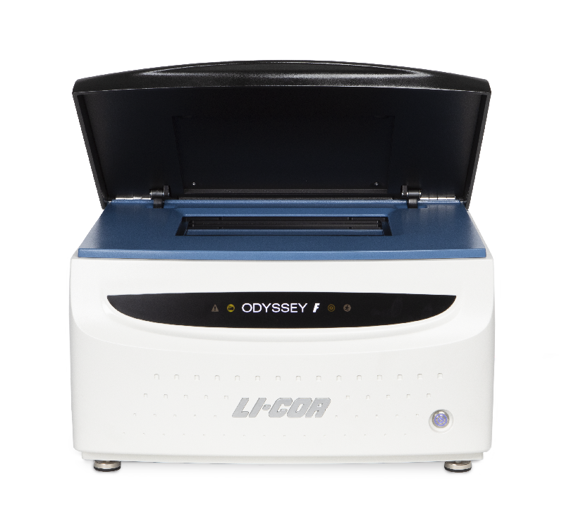

Power On/Off Button: Briefly pressing this button turns the instrument on and off, when the imager is not connected to the Image Studio™ SoftwareLI‑COR® Acquisition Software
| State | Description | Icons |
| OFF | The ODYSSEY text is white, no back lighting. | N/A |
| ON, CONNECTED TO SOFTWARE | The ODYSSEY text is back lit white. The green running icon indicates that the instrument is connected to the software. |  |
| SCANNING | The ODYSSEY text is back lit white. The green running icon indicates that the instrument is connected to the software. The orange clock icon indicates that a scan is in progress. |  |
| OPEN LID (INTERLOCK ACTIVATION) | The ODYSSEY text is back lit white. The green running icon indicates that the instrument is connected to the software. The orange lid icon indicates that the lid is open and that the interlock is activated. |  |
| WARNING | The ODYSSEY text is back lit white. The green running icon indicates that the instrument is connected to the software. The red triangle icon indicates an instrument issue. |  |
Rear Panel
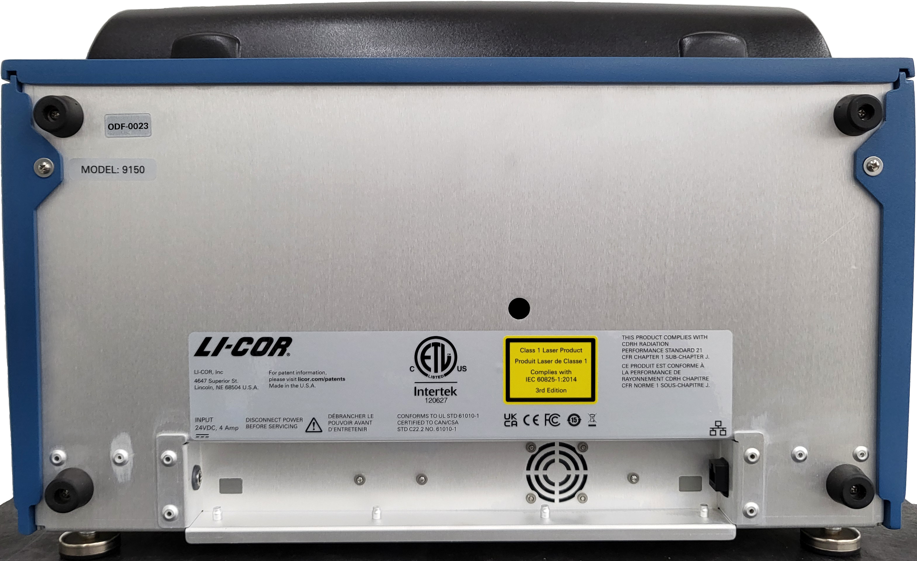
ODF-NNNN (ODF- followed by four numbers). Note: The appearance of your instrument's back panel may vary slightly from the one shown.Scanning Surface
The scanning surface is a 25 cm W x 18 cm D glass plate, upon which the samples to be scanned are placed. The scanning surface is sealed from the instrument interior to prevent moisture from penetrating to the detection optics and electronics below during scanning.