System Overview
External Panels and Controls
Front Panel and Scanning Surface

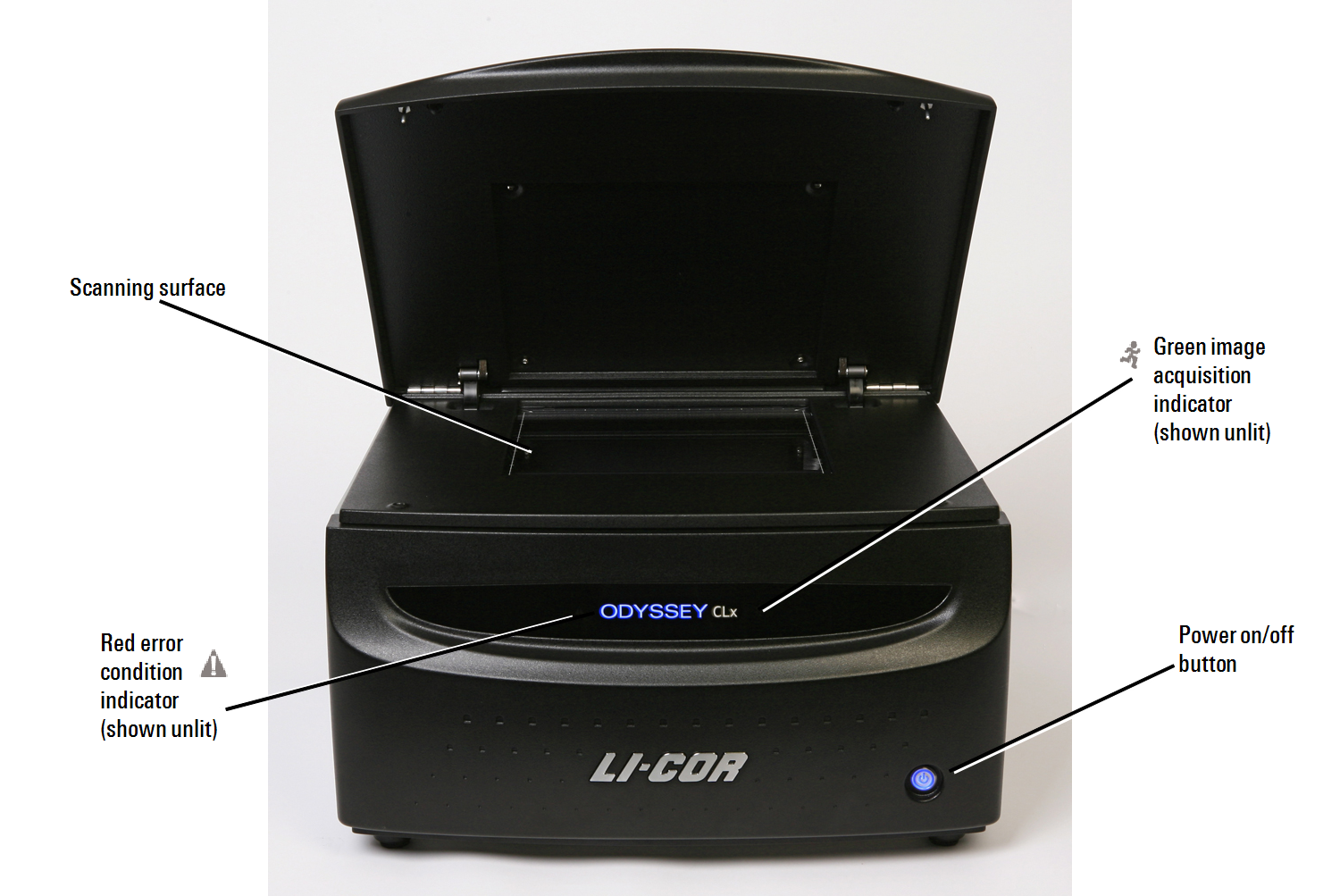
Power On/Off Button: Briefly pressing this button turns the instrument on and off, when the imager is not connected to the Image Studio™ SoftwareLI‑COR® Acquisition Software
Green Image Acquisition Indicator: This indicator light blinks during image acquisition and is continuously on at other times, as long as communication with Image Studio SoftwareLI‑COR Acquisition Software
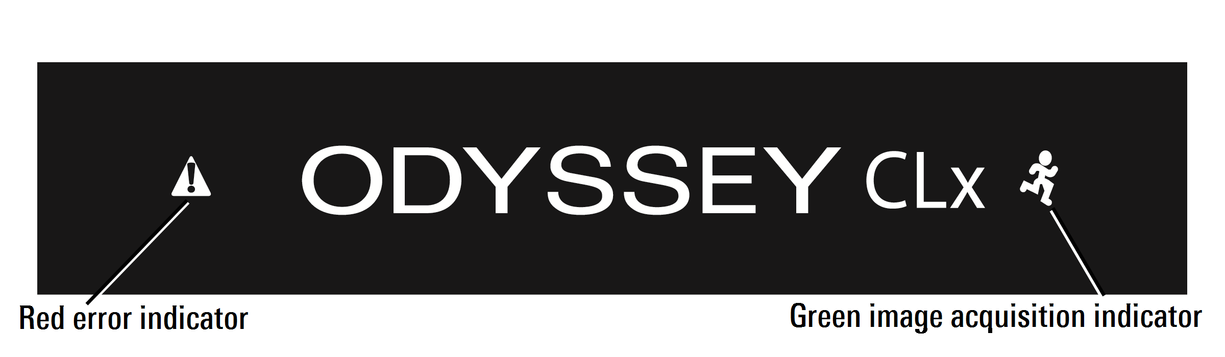

Red Error Indicator: The error indicator light illuminates when a particular process could not be completed.
Rear Panel
Power switch | 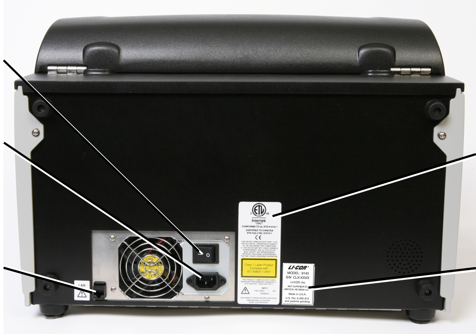 | |
Power receptacle | CDRH regulation compliance label | |
LAN networking port | Manufacturer label |
Scanning Surface

The scanning surface is a 25 cm x 25 cm glass plate (Figure 65), upon which the samples to be scanned are placed. The scanning surface is sealed from the instrument interior so no moisture can penetrate to the detection optics and electronics below.
Optical System Description
Solid state diode lasers simultaneously provide light excitation at 685 and 785 nm. Collimating lenses, optical bandpass filters, and a focusing lens focus and tune the laser beams to produce an excitation spot on the scanning surface. The microscope electronics then modulate the laser beams to discriminate the infrared dye signal fluorescence from background fluorescence. The scanner detection optics focus on the excitation spot and collect light from the fluorescing infrared dyes.
The light is passed to a dichroic mirror after collection by the microscope objective. The mirror splits the light and essentially sorts the fluorescent signals by transmitting the light above 810 nm and reflecting light below 750 nm. Transmitted and reflected light travels two independent paths through optics designed to remove scattered and stray light. The light is ultimately focused onto one of two avalanche photodiodes that converts the light to an electrical signal for processing by the microscope detection electronics.
In the microscope electronics the signal is amplified, filtered, and finally converted to a digital value by an analog-to-digital converter. The digital signal is demodulated, filtered again, and coordinated with the microscope position by a Digital Signal Processor (DSP) to produce the image file.
The entire compact laser/microscope assembly travels on a platform that moves beneath the scanning surface along both the X- and Y-axes. It is adjustable in the Z-dimension to allow for focusing at the scan bed up to 4 mm above the scan bed to accommodate membranes, gels, and microplates.
The Odyssey® DLx Imager has two modes for dynamic range, Automatic and Manual. In Automatic mode the Odyssey DLx acquires images with virtually no saturated pixels on the first attempt with no user adjustments. More than six logs (22 bits) of dynamic range are available for each image. In Manual mode the intensity of each channel can be manually adjusted across a 12 bit dynamic range.