Using auxiliary channels with the aquatic chamber
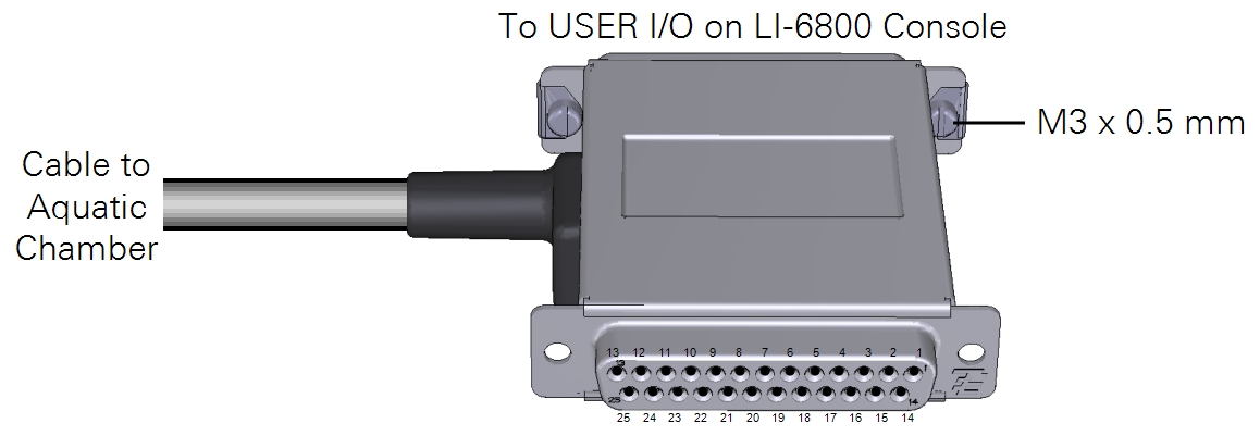
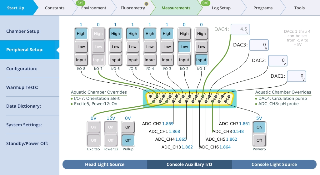
The LI-6800 25-pin connector is used by the aquatic chamber cable, but the connector itself can accept another male 25 pin D-sub (DB25) connector, which can be purchased from many electronics stores or directly from LI-COR. The male-female connector passes through those auxiliary channels not used by the aquatic chamber and blocks access to those that are used by the chamber. Ground (GND), analog ground (AGND), the 12 VDC supply and 5 VDC excitation are all feed-through on this connector and are used by the aquatic chamber. Both the 12 VDC supply (Power12) and 5 VDC excitation (Excite5) need to be enabled for the aquatic chamber to function. These are automatically enabled in software when the aquatic chamber is selected as the aperture for the 6800-01A. Pin assignments are described in Table 10‑5.

Logging the auxiliary channels
When the aquatic chamber is connected and selected as the aperture for the fluorometer, auxiliary channels are logged automatically.
In addition to the inputs and outputs, the interface allows you to activate a 10 kiloohm 0.1% pullup resistor for 5 V biasing of a thermistor on ADC_CH1 (pin 21).
Analog input channels
The eight ADC (analog-to-digital channel) inputs can read from ±5 volts at 16 bit resolution with a sampling rate of 10 Hz. To wire an analog input, select a signal pin (pins 15 to 22) and a ground pin (pin 1 or 24). The sampling rate is fixed at 10 Hz, and thus the resolution is 152.6 µvolts per count. Raw voltages can be logged directly or transformed into more meaningful values using basic equations. This is described in The Constants tab.
If you want to set a controllable parameter to track the reading from an auxiliary channel, see Auto Controls.
Analog output channels
The analog output channels (DAC1 to DAC3) can be set to a fixed voltage in the Start Up > Peripheral Setup > Console Auxiliary I/O tab, or set to a shape (linear, step, sine/4, or sine/2) in Auto Controls and Programs. Output voltages range from -5 to +5 V. To set a fixed voltage, simply enter that value.
Digital outputs and inputs
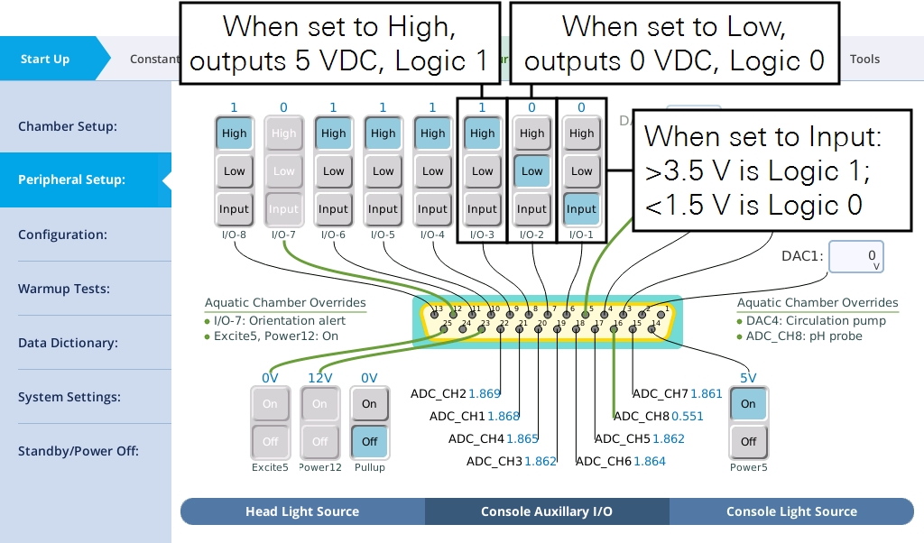
Seven of the eight channels are available for use as digital inputs or outputs.
Tap High to output 5 V and Low to output 0 V through the corresponding pin. When used as a digital input, the voltage must be >3.5 V for logic 1 and <1.5 V for logic 0. The logic signals (pins 6 to 13) provide a very low current. Do not use them to power a device, since that could damage the circuitry. The auxiliary channels are available for use in Programs and graphs.
Auxiliary power supplies
Both of the built-in 12 VDC and 5 VDC power supplies are used by the aquatic chamber. These pass through the connector and are available to power accessories.


