Leaks
In photosynthesis systems, there are two types of leaks: bulk flow and diffusion. Bulk flow leaks occur when there is a hole (apart from the system inlet and outlet) that allows air to move into or out of the system. Diffusion occurs when a particular gas, such as CO2, moves through the walls of the system in response to a concentration gradient.
Bulk Flow Leaks
The pressure inside the leaf chamber is slightly positive so that bulk flow leaks tend not to be a problem. At low flow rates, however, this positive pressure is more than offset in certain parts of the chamber by the chamber circulation fan. This can have dramatic consequences: if the center O-ring on a leaf chamber is missing, for example, ambient air can be sucked into the chamber.
- Check the O-rings
- They have a way of escaping when you are changing chambers, so make sure they are all in place.
- Check the gasket material
- If the white gasket on the light source is flattened, change it. The black gasket material (neoprene) can recover if left uncompressed overnight. When the chamber is not being used, you can preserve your gaskets by adjusting the thumb nut so that the gaskets are not compressed when the chamber is latched.
- Check the seal around leaves and stems
- When the gaskets are compressed around thicker leaves and stems, small gaps will be created. At high flow rates, this may not be a problem, but at lower rates, be sure to seal them with putty or gum.
If bulk flow leaks are there, they will be a bigger problem at low flow rates, than at high flow rates.
Diffusion Leaks
CO2 moves from high concentrations to low concentrations. It does this not only through air, but also through solids, including many plastics and synthetic rubbers. CO2 can pass through Bev-a-line tubing (polyethylene, lined with ethylene vinyl acetate), through gasket material (ethylene and neoprene), and through O-rings (butyl rubber). It goes through just about everything that’s not glass or metal. There are some thin-film materials that have very low permeabilities to CO2, however, such as Teflon, Saran (polyvinylidene chloride), Mylar, and Propafilm® (polypropylene coated with Saran).
Diffusion of CO2 into or out of the LI-6400 leaf chamber is proportional to the difference between the inside and outside CO2 concentrations. It is useful to think of this diffusion leak as a flux of CO2. When the bulk flow rate through the chamber is high, this diffusion flux will affect the chamber concentration very little. When the bulk flow is low, that same diffusion flux will have a much larger effect.
The effects of diffusion in a gas exchange system are proportional to the ratio of surface area (tubing, gaskets) to leaf area (i.e. large leaf area is good, small leaf area is bad). Thus, while you might be able to ignore diffusion problems with a 2x3 or 2x6 chamber, you absolutely cannot ignore them when using the 6400-15 Extended Reach 1-cm Chamber.
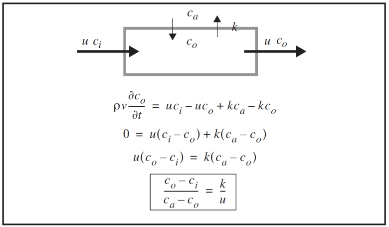
A diffusion model is presented in Figure 4‑11, and predicts a linear relation when normalized leak is plotted against 1/flow rate. (The diffusion leak is (co – ci); the normalizer is the gradient (ca – co).)

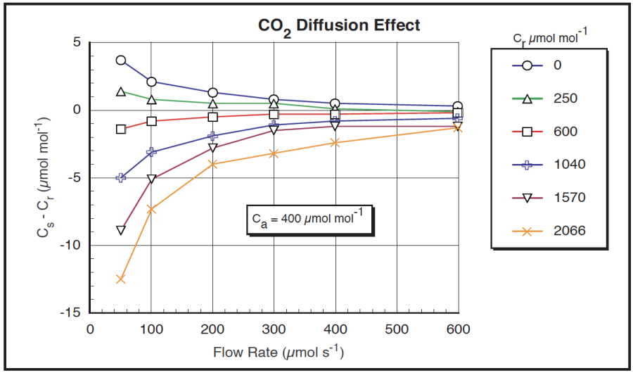
To verify this model, we performed a simple experiment1. We used the CO2 mixer to generate a variety of reference cell CO2 concentrations, and recorded the difference between the sample and reference cell concentrations at various flow rates. (No leaf in the chamber.) We took the following steps to ensure the ambient CO2 concentration was as stable as possible: 1) data collection was done with an AutoProgram, so no one had to be standing there breathing; 2) the instrument was set up in a vacant, well mixed greenhouse; 3) an external fan continually ventilated the chamber; 4) the ambient CO2 concentration was monitored with a second gas analyzer. Sample cell CO2 concentrations were measured by the reference IRGA using the match valve. This eliminated any potential errors due to IRGA drift, since the same IRGA (reference) was used for both sample and reference measurements. The results are plotted in Figure 4‑12.

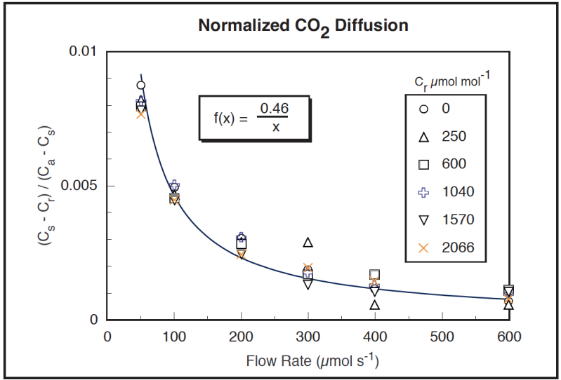
The diffusion effect (Cs – Cr) plotted in Figure 4‑12 is equivalent to the (co – ci) term in the model in Figure 4‑11. Normalizing by the gradient (Ca – Cs) should make this data fall on one curve if the model is correct, and it does to a reasonable degree (Figure 4‑13). Curve fitting yields a diffusion coefficient k of 0.46. (The easiest curve fit is to plot (1/Flow) on the X axis, rather than Flow; k is then the slope of the line.) Note that the outliers tend to be the data collected with the smallest gradient, so uncertainties in what the true gradient was are largest.

In order to correct photosynthesis calculations for the effects of CO2 diffusion, we re-visit the derivation of the photosynthesis equation. The mass balance equation 1‑11 becomes
4‑2
The k(ca – co) term accounts for diffusion. The final equation (1‑10) becomes
4‑3
Note that there are now two “correction terms”: one for transpiration, and one for diffusion. The diffusion correction term is insignificant for measurements with near-ambient CO2 concentrations in the chamber (Table 4‑2). Near the CO2 compensation point it’s a different matter; diffusion becomes significant, and failure to account for it will lead to a large relative overestimation of assimilation rate.
A protocol for measuring at concentrations well away from ambient is:
- Minimize the gradient
- Keep high CO2 (breath) away from the chamber. Keeping the chamber well ventilated will help do this. If possible, collect data with AutoPrograms, so an operator doesn’t need to be nearby.
- Use the diffusion corrected formula for photosynthesis
- Implement the correction in the Compute List.
Recent Developments
Flexis et al2. show evidence that the bulk of diffusion leaks occur at the interface of the two sealing gaskets, and not through the gaskets themselves. They suggest a method of quantifying leak rates by clamping onto leaves rendered photosynthetically inert.
