Preparing for measurements
After installing the components and connecting cables, you are nearly ready for measurements. This section describes additional steps you'll take to prepare for data collection.
Preparing the pH indicator
The indicator solution is usually a 2.0 – 2.5 mM mCP solution made by dissolving m-Cresol Purple sodium salt (C21H17O5SNa) (mCP, molecular weight 404.4153) in DI water or its acid form.
The absorbance ratio of the indicator solution (R = 578A/434A) was adjusted to 0.33 by a small addition of 0.1 N NaOH. 578 nm and 434 nm are the maximum absorption wavelengths for I2- and HI-, respectively. Alternatively, the pH value can be adjusted with 0.1 M NaOH to about 8.0 with a pH glass electrode. Purified mCP indicator analytical grade salt is available from Dr. Robert Byrne’s laboratory in the University of South Florida (as of March, 2025). One may also either purify the mCP using an HPLC column or calibrate a commercially available impure mCP against the purified mCP as explained in Liu et al. (2011).
Dickson et al., 2007 SOP 6b.5 suggest that the final mCP concentration should be < 5 μM. Procedures for preparing the mCP solution at two different concentrations are quoted from two research labs, with Option 2 being at the lower end of the mCP concentration range:
Option 1:
Purified mCP at approximately 2.5×10⁻³ mol/L with pH near 8.0
-
Dissolve 1.011 g purified solid mCP in 1000 mL of DI water.
In practice, scale down to a smaller volume of 200 mL.
-
Mix the compound and the DI water together until the solid is fully dissolved.
About 5 mL of 0.1 M NaOH can be added to help with dissolution.
-
Add more 0.1 M NaOH solution to adjust the pH of mCP dye solution to 8.0.
pH can be roughly monitored by a pH glass electrode on NBS scale. Use 0.1 M HCl solution to adjust backward if pH is too high.
Option 2:
Purified mCP at approximately 2×10⁻³ mol/L with pH near 8.0
- Dissolve 0.08 g mCP in 100 mL deionized water.
- This stock solution is sonicated and 3.25 mL of 0.1 M NaOH is added to achieve a pH of around 8.
In our pH analysis, a 9.8 mL seawater sample is used. Thus, 10 to 15 µL of mCP may be used to achieve a final mCP concentration of about 2.5 μM.
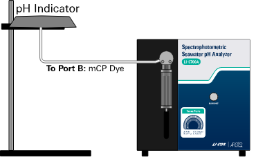
Place the pH indicator (i.e., mCP) bag to the left of the digital syringe. Secure it to a ring-stand that allows gravity to feed the liquid. Connect a piece of 0.04” ID PEEK tube from the pH indicator bag to Port B of the digital pump.
The pH indicator should be stored in a gas-tight bag.
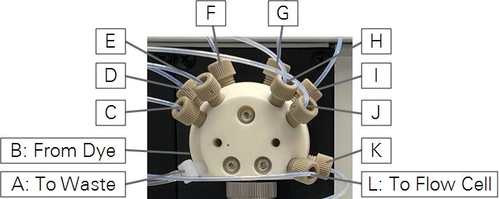
Rotary valve port assignments
| Port | Purpose | Tube |
|---|---|---|
| A | To Waste Container | 1/8" OD (222-21112) |
| B | From pH Indicator | 1/16" OD PEEK; Attached to dye bag |
| C − K | From Samples | 1/16" OD PTFE (222-21111) |
| L | To Flow Cell | 1/16" OD PTFE (222-21111) |

Sample containers
Use sample containers with volume of 250 mL or larger to minimize changes in liquid level inside the sample containers. About 40 mL of sample is needed for the measurement.
Each of the 1/16” OD PTFE tubes from port C − K is for sample seawater. Connect the tubing to your seawater samples for measurement.


Waste collection container
Waste water is discharged from both the digital syringe pump and Cary 60 spectrophotometer after each measurement.
Place a waste collection container (e.g., a 5-liter plastic bottle) behind or beside the analyzer and run the waste tubing into the container. Fix the end of the waste line at a position above the liquid line in the container so that you can see the outlet during analysis. Then you can observe if the waste line is clogged. Check the waste container periodically and empty it as needed.
You may also put the flow cell outlet directly into a sink. Then you can use a smaller waste container for the waste port on the 12-way valve on the control unit.
References
| 1 | Dickson, A.G., Sabine, C.L. and Christian, J.R., Eds. (2007). Guide to best practices for ocean CO2 measurements. PICES Special Publication 3, 191 pp. url: https://www.ncei.noaa.gov/access/ocean-carbon-acidification-data-system/oceans/Handbook_2007/Guide_all_in_one.pdf |

