Taking measurements
During every measurement cycle, the waste solution is discharged both at the end of an analysis from the flow cell and at the beginning of the next analysis from port A. If it does not discharge, stop running the program and check for waste discharge problems (such as blockages in the waste discharge tubing). Do not run the analyzer if the discharge tubes are not flowing freely.
Powering on the components
Power on the Cary 60 spectrophotometer, the LI-5700A control unit, and the computer. Allow the Cary 60 to warm up for about an hour. As the instrument warms up, prepare the rest of the materials.
Setting the digital pump home position
The home position of the syringe is set automatically when it is initialized. However, if there is liquid in the syringe or the outlet tube is restricted during initialization, the system may not correctly identify the home position. To correct this, be sure that liquid can flow freely out of the syringe when the plunger moves, and initialize the syringe again. Repeat the initialization multiple times, if necessary, until the syringe is free of liquid and can identify the correct home position.
Running the program
The following steps are taken on the computer provided with the LI-5700A system.
Note: If the interface does not fit on the screen, adjust the display settings. Press the Windows key ( ), type display, and press Enter. In Display settings, change Scale and Layout to either 125% or 100%.
Initial setup
-
Launch the Spec-pH2 3.0.1T program.
Double click the shortcut icon on the desktop. The software will automatically initialize after starting up.
-
If needed, set the Pump COM port for the pump in the menu.
Typically, only one COM port is presented in the list and the software will select it automatically. Otherwise, you may need to find it:
To find the serial port number, open the Device Manager (press the Windows key
 , type Device Manager, then press Enter). Click Ports (COM & LPT). Look for USB Serial Port (COM#). The serial port numbers are shown beside the ports.
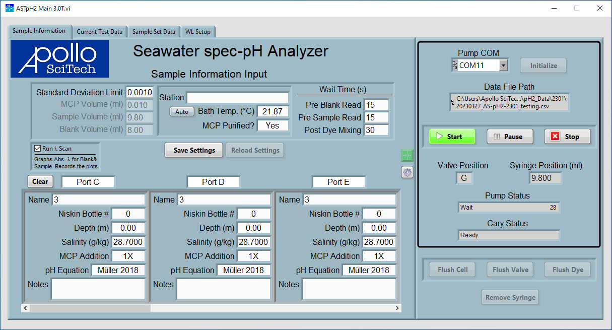
Figure 4‑1. Program initialization. Select the COM port in the upper right and initialize the system. -
Click Initialize to establish communication between the computer and the control unit.
The control unit will operate the pump briefly when the connection is established, indicating the pump has been properly initialized. The pump status and Cary 60 Status will be displayed.
-
Select a directory and enter a file name for the data file.
Entering sample information
-
Under the Sample Information Input, enter measurement parameters and information about the sampling station.
-
Standard Deviation Limit determines the standard deviation requirement of pH value of the best three repeats of the measurements.
-
MCP Volume (ml), Sample Volume (ml), and Blank Volume (ml) set the volume of dye, seawater sample, and sample blank to be drawn during the measurement.
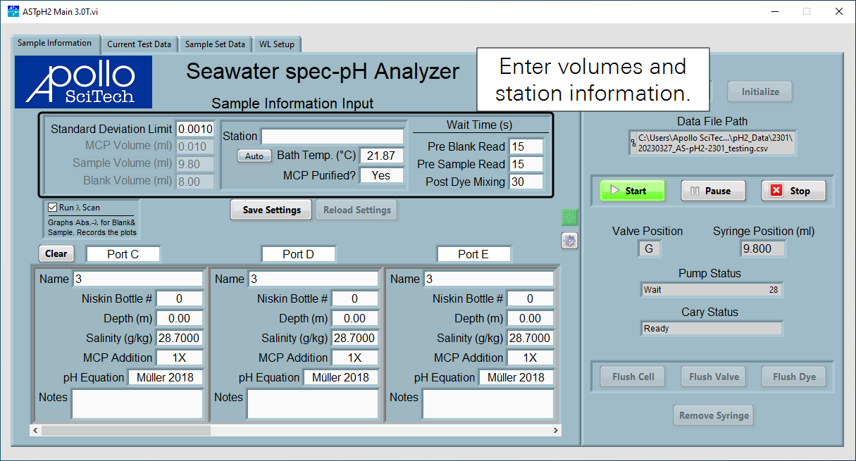
Figure 4‑2. Sample information input. -
-
The Station field accepts a name - choose something memorable.
-
Water Bath Temperature can be set automatically or entered manually.
To enter the temperature, click Auto to change it to Manual to use the entered temperature for the pH calculation. Otherwise, when Auto is selected, the program will automatically take temperature readings from the probe.
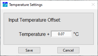
If the temperature readings from the probe are used, an offset can be input by clicking the gear icon in the blue circle in Fig. 5. Input the offset in the pop-up window. Negative offsets are accepted. The bath temperature displayed in the main window has incorporated this offset. The default offset is for the included temperature probe. Change the offset if a new probe is being used or as necessary.
-
Set the Wait Times.
The Pre Blank Read and Pre Sample Read wait times determine the time to wait after the blank sample and sample mixed with mCP is injected in the flow cell and before taking readings. The Post Dye Mixing wait time determines the time to wait after mCP is mixed with the sample in the syringe and before it is injected to the flow cell.
Save Settings and Reload Settings are to save or reload the last saved settings. After entering a new value in any field, click somewhere else in the program to register the new value and the new value will apply when that box is called the next time.
Scanning samples
The box for Run λ Scan allows you to run a scan from 420 nm to 740 nm and save the curve.
Folder names are the same as the corresponding data files. The wavelength files name includes the date and time when the sample was analyzed and the sample ID in the format YY_MM_DD-HH.MM-Sample ID. Note this reading is not used for the final pH calculation and thus may be cleared to save time and storage space.

The lower half of this panel includes the sample information on each port. Scroll to right to other sample ports.
-
Port: Each port on the LI-5700A is identified by the letter (C to K).
-
Name: Enter a name for record keeping. The name is saved in the data file.
-
Niskin Bottle #: The sample number.
-
Depth (m): The depth of the sample collection.
-
Salinity (g/kg): Salinity of the samples.
-
MCP Addition: Allows you to select one of the following:
-
1X: Analyze the sample using the input mCP volume.
-
1X & 2X: Adds two lines in the data table, one with the mCP volume and other one with twice the mCP volume, both from the same sample port. This option is useful when the sample container is large enough to supply samples for both runs.
-
2X: Adds one line in the data table, with twice the mCP volume. This option is useful when two small sample containers from the same location are available.
-
-
pH Equation: Choose a method for the analysis, either Müller 2018, Douglas 2017, Liu 2011, or Mosley 2004.
-
Notes: Free entry for your observations and comments. Notes are stored in the data file along with the measurement data.
Positioning the optical flow cell
You can hear the Cary 60 when it is taking a reading. Click the Current Test Data tab to see the current sample measurement results. Cary 60 will first read Blank.
These readings should be below 0.2. It is acceptable if the reading is somewhat large but stable. Bubbles trapped in the flow cell may lead to large and unstable blank readings. If the optical cell is not aligned with the light pathway, the blank reading can be much higher. The flow cell can be moved along the track. Use a piece of tape and pencil mark the position.
To find the flow cell position with the lowest blank reading:
-
Click the green Read button (see Figure 4‑3).
-
In the pop-up window, click the button Read to read the current absorbance.
-
Move and adjust the flow cell unit along the track gradually and take readings repeatedly until the lowest blank reading is found.
-
Secure the flow cell unit at this position with the thumbscrews.
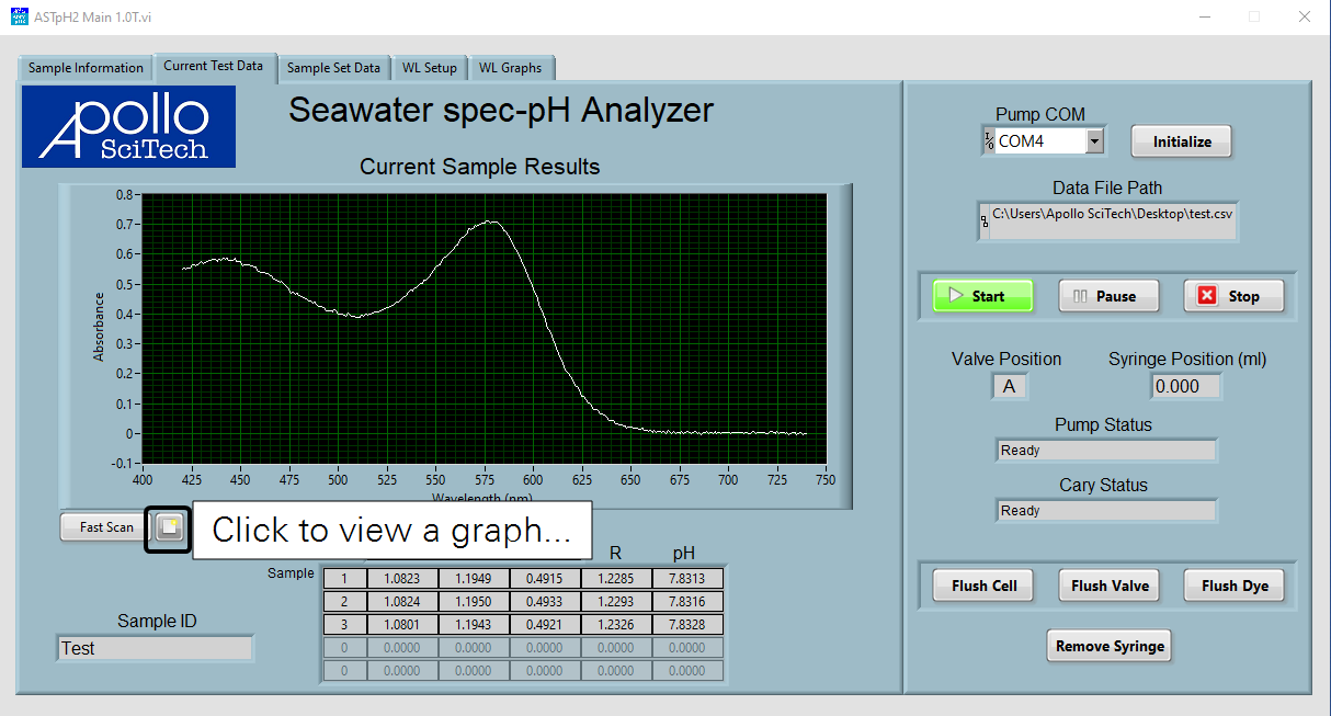
If you run a scan, an absorbance vs. wavelength plot will be displayed in the plot area. Otherwise, absorbances, R values, and pH values are displayed in the table as they become available. Repeats that are used to calculate the average pH are highlighted in light gray while those that are not used for the calculation are highlighted dark blue.
The absorbance value plotted are the difference between the absorbance of the sample and that of the blank, so they do not match the values listed in the table. To view the raw data, click the button to the right of Fast Scan (see Figure 4‑4), which brings up the hidden tab WL Graphs.
If the plot is very jagged, you may need to clean the flow cell. See Cleaning the flow cell for instructions.
Ending the measurement
Before shutting down the instrument, put all sample inlets into DI water and click Flush Valve to clean the valve. Then click Flush Cell to clean the flow cell.
If the analyzer will not be used again for several days, the dye channel also needs to be cleaned. Close the dye bag and disconnect the PEEK tubing from the dye bag and put it into a beaker with DI water. Put the tube for port C in DI water, too. Click Flush Dye, choose flush with dye first. Then click Flush Dye and choose Flush with DI water to clean the dye channel.
If the analyzer will not be used for a long period, drain the water bath inside the temperature-controlled unit and the DI water inside the flow cell. Use the Flush Cell function in the program to flush the flow cell with air.
