Installing the DIC system
The system should be installed in a protected area such as a laboratory or another dedicated space. It should be positioned so that the acid discharge collector will be below the system at all times. When conducting an analysis, you need a carrier gas, an acid solution, and a waste solution container.
Installing the air filter
An air filter is included with the accessories. Install it before using the instrument.
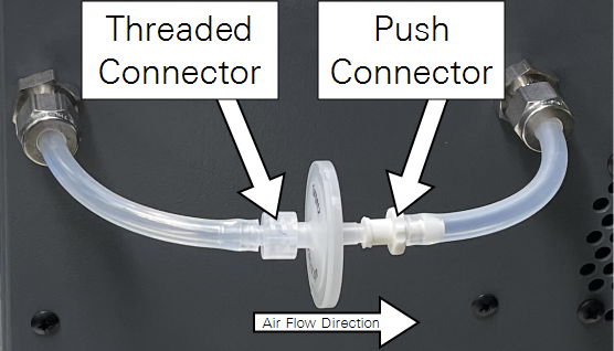
To install the filter on the back of the LI‑53x0A DIC Analyzer:
-
Connect the tube with the Threaded Connector to the connection on the left using a nut and ferrules.
-
Connect the tube with the Push Connector to the connection on the right.
For both connectors, tighten the nuts with two wrenches - a 5/8" wrench holding the immovable part of the connector and a 9/16" wrench turning the nut. Two to three turns are enough. Do not over tighten it or the tube will be crushed.
-
Screw the end of the filter with the marking “0.2 µm” into the Threaded Connector.
-
Push the other end of the filter into the Push Connector.
Connecting data cables
For all DIC models (LI-5300A, LI-5350A, and LI-5370A), connect the DIC module to the computer with the included RS-485-to-USB adapter and cable.
With the LI-5300A and LI-5370A, install the network cable between the gas analyzer and the computer (see Figure 2‑1). With the LI-5350A, install the RS-232-to-USB adapter and cable between the DIC module and the computer (see Figure 2‑2).


Connecting the power supply
The DIC module, computer, and LI-7815 or LI-7825 analyzer (if applicable) include AC power adapters. Connect the adapters to a compatible AC power source. A surge protector may be used to protect the instrument. An uninterruptible power supply (UPS) may be used to prevent unexpected power disruptions.
Note: Two lithium ion batteries are included with the LI-7815 and LI-7825. Install them in the analyzer to ensure it is powered continuously. If batteries are not installed, they need to be charged to approximately 30% to 40% (two bars on the battery charge indicator) within six months of the shipping date and every six months thereafter. Batteries may fail if they are not maintained. If the LI-7815 or LI-7825 analyzer is being stored for a long period of time, maintain each battery to prevent premature failures.


Attaching the carrier gas
The system requires a carrier gas to carry the sample. Use a tank of compressed gas — either 0% CO2 balanced in air (suitable for the LI-5300A, LI-5350A, and LI-5370A) or pure nitrogen (LI-5350A only). A high-quality two-stage regulator capable of delivering a stable pressure of 16 to 18 psi (110 to 124 kPa) is required. Fluctuations of the carrier gas pressure will reduce the accuracy of the analysis. Install a 1 μm hydrophobic air filter between the tank and the DIC module, being mindful of the flow direction indicated on the filter.
Connect the gas regulator to the AIR IN port on the back of the DIC module. Set the regulator outlet to 16 to 18 psi (110 to 124 kPa) and check for leaks.

For the LI-5300A (external LI-7815) and LI-5370A (external LI-7825), use a tank of CO2-free compressed air as the carrier gas. Do not use pure nitrogen because the Trace Gas Analyzer will not initialize properly. If you suspect that the quality of the air is low, install a chemical filter to remove CO2 and H2O. Ascarite II is a good CO2 scrubber and Mg(ClO4)2 can be used to remove trace amount of H2O. A desiccant tube from LI-COR (part number 9960-093) or 20 – 30 mL plastic syringe may be used as a filter chamber for this purpose.
For the LI-5350A (built-in LI-850), use a tank of CO2-free compressed air or pure nitrogen (99.998% pure) as a carrier gas. The LI-7815 and LI-7825 pumps maintain a constant pressure rather than gas flow rate. This results in the unit-to-unit difference in air flow in different analyzers. The DIC analyzer is set to supply an air flow rate slightly higher than that required by the Trace Gas Analyzer to avoid air contamination.
Do not set the carrier gas pressure too low or too high. If the pressure is too low, it will not open the internal mass-flow controller. If the pressure is too high, it may burst connections within the system. A stable gas flow is critical. Inside the instrument, a mass-flow controller regulates the air flow to a constant rate between 200 mL/min and 350 mL/min during sample analysis and 50 mL/min when idle.
Attaching the gas analyzer tubing (LI-5300A and LI-5370A)
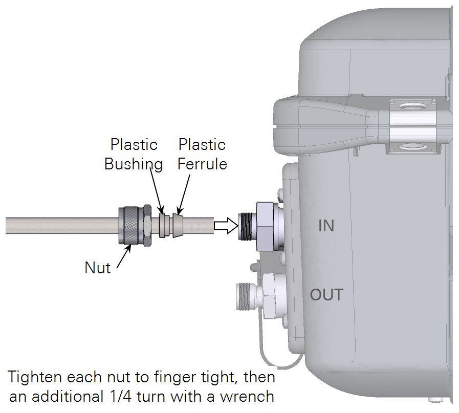
Install a 1-μm filter between the DIC module and the LI-7815 or LI-7825 analyzer. Connect a piece of tubing (1 meter) between the DIC module port labeled TO ANALYZER and the IN port on the LI-7815 or LI-7825 and a second piece between FROM ANALYZER and the OUT port on the LI-7815 or LI-7825.

Use a plastic ferrule and bushing to connect the tube to the compression fitting labeled IN.
Waste collection container
The DIC module discharges waste water before and after each measurement. To collect the waste discharge, place a container such as a 5-liter plastic bottle or large plastic bucket at a level below the analyzer and run the waste tubing into the container. The exit end of the waste tube must be positioned above the liquid line in the container. That way you can see if the waste line is clogged, pinched, or not properly installed. Don’t let the waste line get loose from the container to avoid spills.

Note: Check the waste container periodically and empty it as needed. Note that the waste solution is a relatively strong acid. Discard it with sufficient dilution and follow local regulations to protect waterways.
Note: The waste discharge valve inside the DIC analyzer is normally open. It is necessary to keep the waste discharge tubing in the waste container. Make sure that the waste tubing is properly connected and not pinched, and that waste solution flow is open before using the system.