Configuration grammar
Note: This grammar supports the core features of the instrument, but some functions are not fully described. Contact us if you have questions.
This section describes the protocol used by the instrument to communicate via RS-232 and Ethernet, for both configuration and data output purposes. Commands sent to the instrument have a certain structure that must be followed, and data sent by the instrument comes packaged in a particular way. For example, to set the Bandwidth to 10Hz, the following string
(Outputs(BW 10))
should be sent followed by a line feed character (decimal 10). Each command begins with a left parenthesis ‘(‘, and ends with a right parenthesis ‘)’. Some commands, such as (BW...) contain a single value, while other commands, such as (Outputs...), can contain one or more commands. The parentheses mark the start and stop of the command, and extra characters before or after are ignored, as well as white space (spaces and tabs) before or after the parentheses. This string would work equally as well, for example:
This is ignored ( Outputs (BW 10 )) and so is this
The instrument does not try parsing a command string until a line feed is received. Since "extra" characters are ignored, commands can be terminated with carriage return and line feeds equally as well.
Another example of a command string is
(Outputs(RS232(Freq 10)(Pres TRUE))(BW 5))
In this case, we are setting the RS-232 output frequency to 10Hz, requesting that Pressure be included in the output records, and that the bandwidth be 5 Hz. Notice the 2 parentheses at the end of (Pres TRUE)). This is because (Pres..) and (Freq..) are (RS232..) commands, while (BW..) is not. (BW..) and (RS232..) are both (Outputs..) commands, however, and the “extra” parenthesis at the end of (BW 5)) signals the end of the (Outputs..) command.
An illegal command string would be
(BW 5)
because the (BW...) command is only recognized within the context of an (Outputs...) command.
The configuration grammar is case sensitive. That is, (Outputs(BW 10)) will work, while (outputs(bw 10)) will not.
Who sends what
Not all of the commands in the instrument grammar are really commands. Some are designed to be used by the instrument to package outgoing data. The (Data..) command, or record, might look like this
(Data (CO2D 2.2083146e1)(H2OD 3.5485935e2)(Temp 2.5886261e1)(Pres 9.8157062e1))
This record is showing the latest values of CO2 and H2O mole density (mmol m‑3), temperature (°C), and pressure (kPa). The fields present in a (Data..) record, and how often they are output, is determined by the (Outputs..) command.
Once it has established communications with a host computer (discussed in the next section), the instrument’s RS-232 communications is largely made up of outgoing (Data..) and (Diagnostics..) records. The only other type of records it might send are (Error..) and (Ack..). The (Error..) record is sent whenever the instrument receives a command it cannot parse or recognize, and the (Ack..) record acknowledges a configuration change. It is also used to pass back the new zero or span setting after a (Calibrate..) command.
Command summary
In the following sections, some abbreviations are used:
{int} means an integer value, such as 0, 10, 452, etc.
{float} means any integer or floating point value, such as 0, 3.14159, 1E-7, -3.47e-09, etc.
{string} means anything (< 40 characters) contained by double quotes, such as "Hey, you!"
{ item1 | item2 | item3 } means you must include one of the items in the list.
{bool} - { TRUE | FALSE }
The (Outputs..) command
(Outputs..) is used to configure the items pertaining to data output, including the bandwidth, delay time, DACs (digital to analog convertors), the RS-232 port, Ethernet and USB Logging. The actual RS-232 and Ethernet output uses the (Data..) record described in Table E‑2.
| Command | Subcommands | Remarks | |||
|---|---|---|---|---|---|
| (Outputs | (BW {5 | 10 | 20}) | ) | Sets instrument bandwidth to 5, 10, or 20 Hz. | ||
| (Delay {int}) | Output delay interval (0 to 32), where each interval is 1/150 seconds. This is added to the 220 ms system delay. | ||||
| (Dac1 (Dac2 (Dac3 (Dac4 (Dac5 (Dac6 |
(Source {List})1 | ) | The variable that drives the DACs (digital to analog converters) | ||
| (Zero {float}) | Value that corresponds to 0 Volts output | ||||
| (Full {float}) | Value that corresponds to 5 Volts output | ||||
| (SDM | (Address {int}) | ) | SDM address (0 thru 14). | ||
| (Outputs | (RS232 | (Baud {9600 | 19200 | 38400}) | ) | ) | Baud rate for RS-232 |
| (Freq {float}) | Output frequency of (Data..) records in Hz. Usable values: 0.0 thru 20.0 | ||||
| (Labels {bool}) | |||||
| (DiagRec {bool}) | |||||
| (EOL {"hex code(s)"}) | User defined termination character(s) for data record in "hex" (e.g. "0D0A" would be carriage return line feed). Default is "0A" = line feed. | ||||
| ({List2} {bool}) | These commands determine what is included in the (Data output record | ||||
| (ENet | (Freq {float}) | ) | |||
| (Labels {bool}) | |||||
| (DiagRec {bool}) | |||||
| (EOL {"hex code(s)"}) | |||||
| ({List1} {bool}) | |||||
| (Logging | (Freq {1|2|5|10|20} | ) | |||
| (Split {0|15|30|60|90|120|240|1440}) | |||||
| (Zip {bool}) | |||||
| (Full { Delete | DeleteAll | Stop }) | |||||
| (7700Status {bool}) | |||||
| ({List3} {bool}) | |||||
| (Metadata{see below}) | |||||
Metadata commands
| Command | Subcommands | |||
|---|---|---|---|---|
| (Metadata | (Log {bool}) | ) | ) | |
| (Site | (site_name {string}) | |||
| (altitude {float}) | ||||
| (gpsformat {DDD MM SS.SSS | DDD MM.MMM | Decimal Degrees}) | ||||
| (latitude {+|- xxxd xx' xx.xxx"} | |
||||
| (longitude {+|- xxxd xx' xx.xxx"} | |
||||
| (canopy_height {float}) | ||||
| (displacement_height {float}) | ||||
| (roughness_height {float}) | ||||
| (Station | (station_name {string}) | |||
| (Instruments | (instr_1_manufacturer {string}) | |||
| (instr_1_model {string}) | ||||
| (instr_1_height {float}) | ||||
| (instr_1_wformat {uvw|polar_w|axis}) | ||||
| (instr_1_wref {spar|axis}) | ||||
| (instr_1_north_offset {float}) | ||||
| (instr_2_manufacturer {string}) | ||||
| (instr_2_model {string}) | ||||
| (instr_2_height {float}) | ||||
| (instr_2_north_separation {float}) | ||||
| (instr_2_east_separation {float}) | ||||
| (instr_2_vertical_separation {float}) | ||||
| (instr_3_manufacturer {string}) | ||||
| (instr_3_model {string}) | ||||
| (instr_3_height {float}) | ||||
| (instr_3_north_separation {float}) | ||||
| (instr_3_east_separation {float}) | ||||
| (instr_3_vertical_separation {float}) | ||||
(EOL "{hex code(s)"})
End of Line character. Enter hex value in double quotes.
Example:
(Outputs(RS232(EOL "0D0A”)))lf
would terminate data strings with a carriage return and a line feed.
(Ndx {bool})
Determines whether an index value is transmitted or not.
Example:
(Outputs(RS232(Ndx TRUE)))lf
would cause the data stream to contain an index value. The index value is incremented approximately every 6.7 milliseconds (e.g. 150 Hz) and ranges from approximately -2.0E8 to +2.0E8.
(DiagRec {bool})
Controls whether independent (Diagnostic) text records are ever sent. If TRUE, operates normally (1/second or on a change). If FALSE, never sends a Diagnostic record.
Transmitted:(Outputs(RS232(DiagRec TRUE)))lf
Received:(Diagnostics (SYNC TRUE)(PLL TRUE)(DetOK TRUE)(Chopper TRUE)(Path 61))
(DiagVal {bool})
Controls whether or not a 1 byte diagnostic value (0-255) is output (same as SDM diagnostic value) in the (Data stream. "Diag" is used for the label when (Labels TRUE is set.
Example:
Transmitted:(Outputs(RS232(DiagVal TRUE)))lf
Received:(Data... (Diag 249...))
NOTE: The (DiagRec and the (DiagVal are two separate outputs and are independent of one another.
(Labels {bool})
This command controls whether or not data labels are transmitted with the data stream. Default is TRUE, and this means that data are transmitted in the normal (Data) format record. When (Labels FALSE), however, data output are values only and are tab-delimited. To maximize available bandwidth, when (Labels FALSE), a data record might appear as
15.1234<tab>354.123<tab>101.3<tab>249<eol>
The following are several examples of data formatting. The command string sent to the instrument is terminated with a line feed character.
EXAMPLE (Labels TRUE) data format
Transmitted to instrument
(Outputs(RS232(Freq 1)(EOL "0D0A")(Ndx TRUE)(DiagRec FALSE)(DiagVal TRUE)(Labels TRUE)))lf
Received from the instrument
(Data (Ndx 1545)(DiagVal 250)(CO2Raw 1.5386712e-1)(CO2D 3.2183277e1)(H2ORaw 3.5775542e-2)(H2OD 1.9687008e2)(Temp 2.4227569e1)(Pres 9.8640356e1)(Aux 0)(Cooler 1.5756724))(Data (Ndx 1809)(DiagVal 250)(CO2Raw 1.5380490e-1)(CO2D 3.2162146e1)(H2ORaw 3.5757541e-2)(H2OD 1.9677452e2)(Temp 2.4227569e1)(Pres 9.8543587e1)(Aux 0)(Cooler 1.5750400))
EXAMPLE (Labels FALSE) Data format
Notice how this format is much cleaner and reduces the overhead of redundant label transmissions. The data selected for output data record is accomplished with the (Outputs(RS232(CO2Raw TRUE)...)) command.
Transmitted to the instrument
(Outputs(RS232(Freq 1)(EOL "0D0A")(Ndx TRUE)(DiagRec FALSE)(DiagVal TRUE)(Labels FALSE)))lf
Received from the instrument
252 250 0.15401 32.2167 0.03569 196.703 24.33 98.6 0 1.5730
511 250 0.15404 32.2174 0.03572 196.816 24.42 98.5 0 1.5683
765 250 0.15402 32.2342 0.03579 196.995 24.49 98.6 0 1.5703
1033 250 0.15400 32.2097 0.03571 196.771 24.63 98.5 0 1.5724
1288 250 0.15405 32.2341 0.03578 196.838 24.76 98.5 0 1.5734
1544 250 0.15406 32.2385 0.03575 196.782 24.72 98.5 0 1.5724
Examples:
To set the instrument to output only CO2 and H2O molar densities once every 2 seconds:
(Outputs(RS232(Freq .5)(Pres FALSE)(Temp FALSE)(Aux FALSE)(CO2Raw FALSE)(CO2D TRUE)(H2ORaw FALSE)(H2OD TRUE)(Cooler FALSE)))
To configure DAC #1 to output CO2 mole density with this scaling: 0V = 12 mmol m‑3, and 5V = 15 mmol m‑3.
(Outputs(Dac1(Source CO2MMOL)(Zero 12)(Full 15)))
Data and status records
The (Data..) and (Diagnostics..) records are the vehicles with which the instrument outputs data through its RS-232 port. The frequency with which it outputs (Data..) records is determined by the (Outputs(RS232(Freq..))) command. Data and status record formats are determined by the (Outputs(RS232 (boolean controlled command structure. (EOL {"hex codes"}) and (Labels {boolean}) determine the termination characters and whether or not (Data labels are output.
Examples:
A typical (Data..) output record, with all items present, is shown below:
(Data (Ndx 215713)(CO2Raw 1.2831902e-1)(CO2D 2.2083146e1)(H2ORaw 5.5372476e-2)(H2OD 3.5485935e2)(Temp 2.5886261e1)(Pres 9.8157062e1)(Aux 0)(Cooler 1.0537354))
A typical (Diagnostics..) record is shown below:
(Diagnostics (Sync TRUE)(PLL TRUE)(DetOK TRUE)(Chopper TRUE)(Path 63))
Data polling (software and hardware)
A software command using the ENQ character (0x05) is available to query the instrument for a data record over RS-232. When transmitted to the instrument, via RS-232, the record is built as presently defined (Labels TRUE or FALSE, etc.), and is added to the serial output queue. This software command is normally used when the update frequency is set to zero, as shown in the command below.
(Outputs (RS232 (Freq 0)(DiagRec FALSE)))lf
The instrument also supports toggling of the Clear To Send (CTS) line to request a data record. This hardware polling would be normally used when the update frequency is set to 0 as described above. Since the CTS line is an input, the host software should toggle the Request To Send (RTS) line from the host computer. This method of transmitting a data record occurs when the CTS line goes from low to high.
Users familiar with programming RS-232 interfaces may already understand that RS-232 logic TRUE (1) is considered a low (or negative) voltage and logic FALSE (0) is considered a high (or positive) voltage. Thus, the CTS toggle sequence would look like:
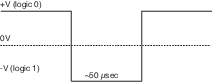
Data are updated to RS-232 at 20 Hz. If the CTS line is toggled, record will be output the next time one is ready. The CTS line is pin 7 on the LI-COR RS-232 Cable, part number 392-10268. The RS-232 serial pin-out from a DB9 connector on an AT style computer is defined as:
| Pin | Signal Description | Function | Signal at Device |
|---|---|---|---|
| 1 | DCD | Data Carrier Detect | Input |
| 2 | RD | Received Data | Input |
| 3 | TD | Transmit Data | Output |
| 4 | DTR | Data Terminal Ready | Output |
| 5 | SG | Signal Ground | |
| 6 | DSR | Data Set Ready | Input |
| 7 | RTS | Request To Send | Output |
| 8 | CTS | Clear To Send | Input |
| 9 | RI | Ring Indicator | Input |
A possible wiring configuration using the LI-COR RS-232 cable, part number 392-10268 to a computer would be:
| LI-COR CABLE | DB9 ON HOST COMPUTER | LI-COR CABLE |
|---|---|---|
| Function | PIN | Function |
| Ground | PIN 5 | Ground |
| Receive Data | PIN 3 | Transmit Data |
| Request To Send | PIN 8 | Clear To Send |
| Transmit Data | PIN 2 | Receive Data |
| Clear To Send | PIN 7 | Request To Send |
| Data Terminal Ready | PIN 6 | Data Set Ready |
Note about embedded software RS-232 communication priorities
The RS-232 hardware and software trigger does not tap directly into the same data stream that is output to the DAC's and the SDM. The trigger actually sends a request to the instrument to output a single data record over the RS-232 port. The processing that is incurred to do this is relatively lengthy. The RS-232 task is also a low priority, so considerable latency could occur. If you want to output data that is tightly synchronized to an input stimulus you should use the SDM output or sample a DAC output based on your trigger; don't use RS-232.
The (Inputs..) command
The (Inputs..) command is used to scale the Auxiliary input channel, and to determine how pressure and temperature are measured by the instrument.
| Command | Subcommands | Remarks | |||
|---|---|---|---|---|---|
| (Inputs | (Pressure(Temperature | (Source { Aux | Measured | UserEntered }) | ) | ) | How it is determined |
| (Val {float}) | Fixed value, for “UserEntered” | ||||
| (Aux | (A {float}) | ) | A and B are the Slope and Intercept respectively Name: Used to denote the type of input. For example, U, V, W, Ts. Units: The units of the data after the slope and intercept are applied. |
||
| (B {float}) | |||||
| (Name{string}) | |||||
| (Units{string}) | |||||
| (Aux2 | (A {float}) | ) | |||
| (B {float}) | |||||
| (Name{string}) | |||||
| (Units{string}) | |||||
| (Aux3 | (A {float}) | ) | |||
| (B {float}) | |||||
| (Name{string}) | |||||
| (Units{string}) | |||||
| (Aux4 | (A {float}) | ) | |||
| (B {float}) | |||||
| (Name{string}) | |||||
| (Units{string}) | |||||
Examples:
To make pressure fixed at 92 kPa, send this:
(Inputs(Pressure(Source UserEntered)(Val 92)))
To measure temperature from a linearized thermistor connected to the Auxiliary input, where 0 volts is 0 °C, and 5 volts is 50 °C, send this:
(Inputs(Aux(A 10)(B 0))(Temperature(Source Aux)))
To measure pressure and temperature normally, using the built-in sensors, send this:
(Inputs(Pressure(Source Measured))(Temperature(Source Measured)))
The (Calibrate...) and (Coeffs...) commands
The (Calibrate..) and (Coeffs..) commands control zeroing, spanning, and factory calibration coefficients. The (Date subcommand must be present, and (Val must be absent to perform (ZeroH2O and (ZeroCO2. For (SpanCO2 and (SpanH2O, (Date and (TDensity must be present, and (Val must be absent to trigger a calibration.
| Command | Subcommands | Remark | |||
|---|---|---|---|---|---|
| (Calibrate | (ZeroH2O (ZeroCO2 |
(Val {float}) | ) | ) | For setting the zero directly. If not present will trigger a calibration. |
| (Date {quoted string}) | The date field triggers the instrument to do a zero immediately. The new value will be returned in an (Ack..) record. | ||||
| (SpanCO2 (Span2CO2 (SpanH2O (Span2H2O |
(Val {float}) | ) | For setting the span directly. If not present will trigger a calibration. | ||
| (Target {float}) | Target value in ppm for CO2, or °C for H2O (for reference purposes). | ||||
| (TDensity {float}) | Target value in mmol m‑3. (For computational purposes). | ||||
| (Date {quoted string}) | |||||
| (MaxRef | (CX {int}) | ) | Maximum expected value of raw reference signal Aco at -40 °C. | ||
| (WX {int}) | Maximum expected value of raw reference signal Awo at -40 °C. | ||||
| (Date {quoted string}) | |||||
| Command | Subcommands | Remark | ||||
|---|---|---|---|---|---|---|
| (Coeffs | (Current | (SerialNo {quoted string}) | ) | The 72H-xxxx head number. | ||
| (Band (A {float})) | The band broadening coefficient (1.15). | |||||
| (CO2 | (A {float}) | ) | These values are found on the calibration sheet. SD1, SD2, and SD3 are b1, b2, and b3 from equation 11‑17. | |||
| (B {float}) | ||||||
| (C {float}) | ||||||
| (D {float}) | ||||||
| (E {float}) | ||||||
| (XS {float}) | ||||||
| (Z {float}) | ||||||
| (SD1 {float}) | ||||||
| (SD2 {float}) | ||||||
| (SD3 {float}) | ||||||
| (H2O | (A {float}) | ) | These values are found on the calibration sheet. SD1, SD2, and SD3 are b1, b2, and b3 from equation 11‑13. | |||
| (B {float}) | ||||||
| (C {float}) | ||||||
| (XS {float}) | ||||||
| (Z {float}) | ||||||
| (SD1 {float}) | ||||||
| (SD2 {float}) | ||||||
| (SD3 {float}) | ||||||
| (Pressure | (A0 {float}) | |||||
| (A1 {float}) | ||||||
| (MaxRef | (B {float}) | |||||
| (C {float}) | ||||||
Examples:
- To set the CO2 zero right now (with CO2-free gas flowing though it, of course), send this:
- (Calibrate(ZeroCO2(Date “11 Aug 2016 at 2:15”)))
- Note 1: The data value can be any string, so “My Birthday” is equally valid.
- Note 2: The new value of zero will be sent in the next
(Ack(Val..))record. (See Table 2). - To force the H2O channel to use the value 0.96 for its zero, send this:
- (Calibrate(ZeroH2O(Val 0.96)))
- To make the instrument set its CO2 span right now, with 400 µmol mol‑1 flowing through the calibration tube, first compute the target density (solved for C).
- If the temperature is 23°C, and the pressure 98kPa, then the mode density is 15.92 mmol CO2 m‑3. Then send the following:
- (Calibrate(SpanCO2(Target 400)(Tdensity 15.92)(Date "14 Sept 2015")))
The Program Reset command
(Program(Reset TRUE)) is the equivalent of pressing the reset button on the main board. It is generally only used to access lower level software for updating the embedded program, or when the instrument is not responding normally.
| Command | Remarks |
|---|---|
| (Program (Reset TRUE)) | Sending this will force the software to reset. This is equivalent to pressing the reset button on the LI-7550 inside panel. |
The Network command
The Name can only include upper and lower case letters (A to Z and a to z), numbers (0 to 9), the dash character (-), and the period (.). Names that do not comply with this constraint will cause communication problems.
| Command | Subcommands | Remarks | |||
|---|---|---|---|---|---|
| (Network | (Name {string}) | ) | Hostname Address type: dhcp | static |
||
| (IP | (Type {dhcp | static} | ) | |||
| (Address {xxx.xxx.xxx.xxx}) | |||||
| (Netmask {xxx.xxx.xxx.xxx}) | |||||
| (Gateway {xxx.xxx.xxx.xxx}) | |||||
| (MAC {xx:xx:xx:xx:xx:xx}) | |||||
The Clock command
| Command | Subcommands | Remarks |
|---|---|---|
| (Clock | (Date {}) | System date |
| (Time {}) | System time | |
| (PTP {off | automatic | slaveonly | preferred}) | Precision Time Protocol setting | |
| (Zone {4}) | Time zone |
The Query command
The Query (?) command is used to query the instrument for any configuration parameter individually, as well as any node in the configuration tree.
| Command | Remarks |
|---|---|
| (Outputs ?) (Calibrate ?) (Coef ?) (Outputs ?) (Data ?) (Diagnostics ?) (EmbeddedSW ?) (Inputs ?) (Info ?) (Network ?) (MeteoDevices ?) (MeteoSensors ?) |
The query for individual parameters works only for configuration parameters and not data or diagnostic information. All commands are followed by a line feed (lf). |
Examples:
The query (Outputs(RS232(Freq ?)))lf would respond:
(Outputs (RS232 (Freq 5)))
whereas the query (Calibrate ?)lf causes a Calibrate record to be put in the output queue.
Example Response:
(Calibrate (ZeroCO2 (Val 0.8945)(Date 26 08 2009 10:37))(SpanCO2 (Val 1.0068)(Target 597.2)(Tdensity 23.154)(Date 26 08 2009 11:00))(Span2CO2 (Val 0.0)(Target )(Tdensity )(ic 0.106207)(act 0.105489)(Date 4Cal))(ZeroH2O (Val 0.791075)(Date 26 08 2009 11:20))(SpanH2O (Val 1.00585)(Target 12.00)(Tdensity 447.421)(Date 26 08 2009 11:37))(Span2H2O (Val 0.0)(Target )(Tdensity )(iw 0.059434)(awt 0.0590885)(Date 4Cal)))
(Coef ?)lf causes a Coefficients record to be put in the output queue.
Example Response:
(Coef (Current (SerialNo 75H-Beta6)(Band (A 1.15))(CO2 (A 1.56704E+2)(B 2.15457E+4)(C 4.33894E+7)(D -1.24699E+10)(E 1.75102E+12)(XS 0.0023)(Z 0.0002))(H2O (A 5.24232E+3)(B 3.91896E+6)(C -2.33026E+8)(XS -0.0009)(Z 0.0185))(Pressure (A0 56.129)(A1 15.250))(DPressure (A0 1.0)(A1 0.0))))
(Outputs ?)lf causes a Outputs record to be put in the output queue.
Example Response:
(Outputs (BW 10)(Delay 0)(SDM (Address 7))(Dac1 (Source NONE)(Zero -5e-2)(Full 4e-1))(Dac2 (Source PRESSURE)(Zero -1e-1)(Full 4e-1))(RS232 (Baud 38400)(Freq 0)(Pres TRUE)(Temp TRUE)(Aux TRUE)(Cooler TRUE)(CO2Raw TRUE)(CO2D TRUE)(H2ORaw TRUE)(H2OD TRUE)(Ndx TRUE)(DiagVal TRUE)(DiagRec FALSE)(Labels FALSE)(EOL "0D0A")))
(Data ?)lf causes a Data record to be put in the output queue. (Note that an ENQ (0x05) will do the same thing...)
Example Response:
(Data (Ndx 2471)(DiagVal 250)(CO2Raw 1.6319131e-1)(CO2D 3.5119712e1)(H2ORaw 3.1672954e-2)(H2OD 1.7067077e2)(Temp 2.3874512e1)(Pres 9.8735609e1)(Aux 0)(Cooler 1.5630015))
(Diagnostics ?)lf causes a Diagnostics record to be put in the output queue.
Example Response:
(Diagnostics (SYNC TRUE)(PLL TRUE)(DetOK TRUE)(Chopper TRUE)(Path 65))
(EmbeddedSW ?)lf causes an EmbeddedSW record to be put in the output queue.
Example Response:
(EmbeddedSW (Version 4.0.0)(Model LI‑7x00RS CO2/H2O Analyzer)(DSP 4.0.0)(FPGA 4.0.0|))
(Inputs ?)lf causes an Inputs record to be put in the output queue.
Example Response:
(Inputs (Pressure (Source Measured)(UserVal 9.8000002e1))(Temperature (Source Measured)(UserVal 2.5000000e1))(Aux (A 1)(B 0)))
The MeteoDevices command (biomet station)
| Command | Subcommands | Remarks | |
|---|---|---|---|
| (MeteoDevices | (DevList {string:string...}) | ) | Colon delimited list of devices on the network (subnet) |
| (Device {string}) | Current connected device | ||
| (DeviceState {0|1}) | 0=not connected 1=connected |
||
| (SyncClock {bool]) | When TRUE, the clock on the 9210B will get updated with the time of the LI-7550 | ||
The MeteoSensors command (biomet sensors)
| Command | Subcommands | Remarks | |
|---|---|---|---|
| (MeteoSensors(Sensor | (Name {string}) | ) | Name of sensor, Defined in Coms Tag |
| (Type {int}) | Type of sensor | ||
| (Units {int}) | Units |
The connection protocol
The purpose of this section is to describe the protocol used to establish communications with the instrument when it is operating in an “unknown” mode. That is, when the baud rate is not known, nor are any other details about the instrument’s configuration.
For simple data collection, the instrument can be configured with the PC software, and you will not have to deal with this protocol at all. If you want to write your own interface program or driver for the instrument, and you want to get the instrument to send its configuration to you, then this protocol must be used.
- Set a break condition on the RS-232 line. 500 ms should be sufficient.
- The instrument will cease normal activity, change its baud rate to 9600 baud, and begin to send ASCII ENQ characters (decimal 05) at a rate of 2 Hz for up to 10 seconds. Before 10 seconds are up, the host should:
- Send an ASCII ACK character (decimal 06) to the instrument.
- Upon receipt of an ACK, the instrument will output its current configuration, terminated with a line feed (decimal 10). After this is sent, the instrument will resume its normal operation, except it will remain at 9600 baud.
- The host can then send the desired configuration changes, if any, to the instrument.
- If the configuration change involves a baud rate change, the instrument will send its (Ack..) record before changing baud rates.