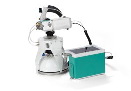
Installing the soil chamber
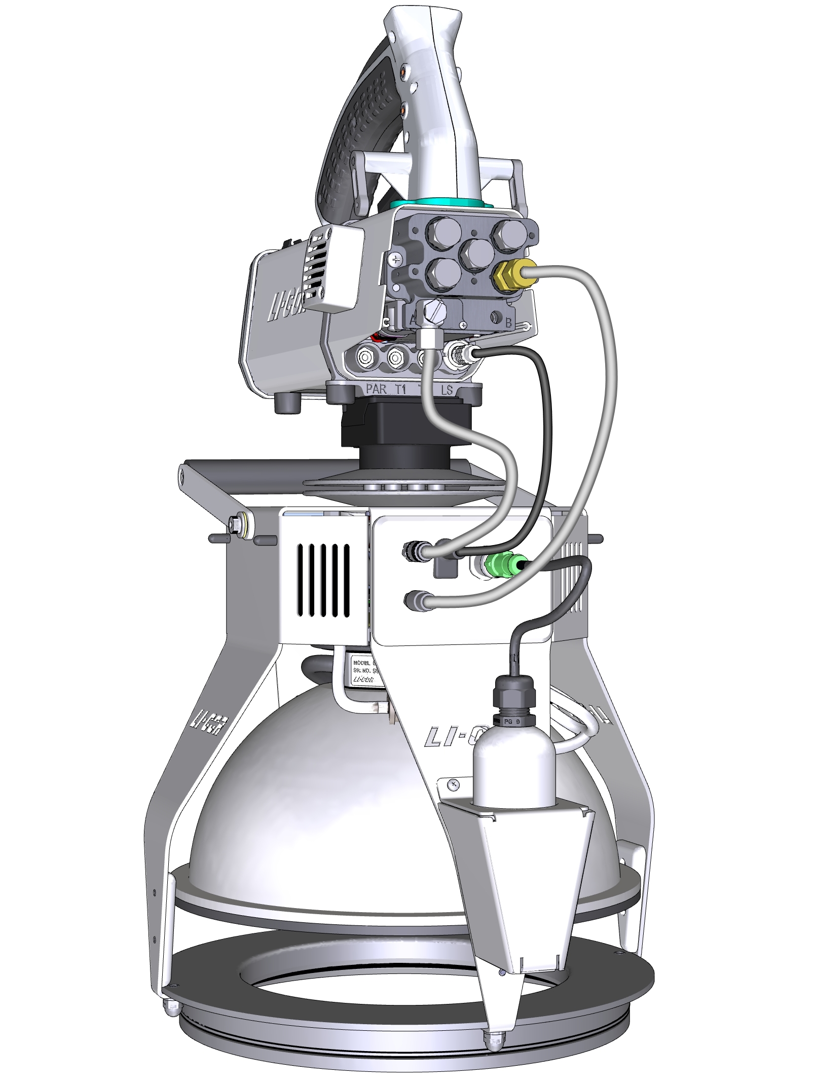
The basic procedure involves attaching the LI-6800 head to the chamber, attaching the air tubes to the head, connecting the data cable, and attaching the soil probe. To take a measurement, you'll need to install soil collars at the measurement locations (at least 6 hours before measurements) and configure the software to take the measurement. To attach the chamber:
- Attach the Head Mounting Bracket to the head.
- Attach the Custom Chamber Adapter.
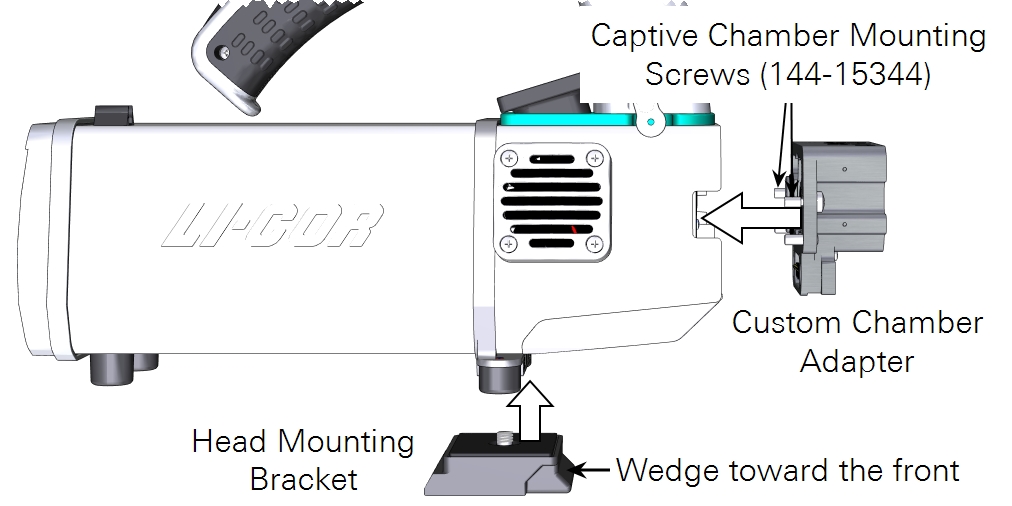
- Install one brass Swagelok fitting and one steel 90° Swagelok fitting onto the Custom Chamber Adapter.
- Each plug and fitting must have an O-ring. The O-rings are preinstalled, but it is a good idea to verify that they are in place prior to installing a cap or fitting. Although not required, we recommend installing four steel cap plugs on the unused fittings to prevent debris from entering the adapter.

- Install the air inlet and air outlet tubes on the adapter plate Swagelok fittings.
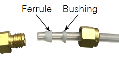
- The Swagelok fittings have metal ferrules. Remove the metal ferrules and set them aside for safekeeping. Retrieve two 30-cm pieces of tube and two plastic ferrule sets (part number 300-05375) from the accessories kit. Install the Bev-a-line tube with plastic ferrules and bushings in the Swagelok fittings (see Figure 11‑4). Tighten each tube snugly.
- Attach the head to the chamber.
- The mounting bracket clips into place on the top of the soil chamber.
- Attach the tubes from the head to the chamber.
- Each tube connects to a corresponding connector on the chamber.
- Attach the chamber cable to the LS connector on the head.
- Remove the connector cover to access the connectors. Reinstall the cover after connecting the cable.
- Attach the soil sensor or HydraProbe (optional).
- The options are described in Connecting external soil sensors.
- Attach the head cable between the LI-6800 head and console.

Note: We suggest that you do not connect the tube between the console and head. When the console starts up, the console circulation pump may start running. If the tube is in place and the cap plugs are installed on the custom chamber adapter plate, the console pump could pressurize the system and activate the relief valve in the head.
Now you are ready to power on the LI-6800 system.
Connecting external soil sensors
There are three options for soil moisture and temperature measurements: the Stevens HydraProbe, a soil temperature thermocouple, or none. Soil moisture and temperature are not essential for the flux calculation, but they can provide useful ancillary data.
Stevens HydraProbe
The Stevens HydraProbe offers the simplest connection and most informative data. It measures soil moisture content and temperature. The HydraProbe II uses the SDI-12 communication protocol, and no configuration is necessary. Connect the cable and power on the LI-6800. The cable connector has a marking that faces up and a key that must be aligned before the connector can be tightened.
Type E thermocouple
You'll connect the thermocouple adapter cable to either thermocouple jack on the head (T1 or T2). The thermocouple adapter cable has a connector for an Omega™ Quick Disconnect Type E Chromega™-Constantan thermocouple. The adapter cable (part number 9968-162) and a compatible thermocouple (current part number 9982-080; discontinued part number 6000-09TC) can be purchased from LI-COR.
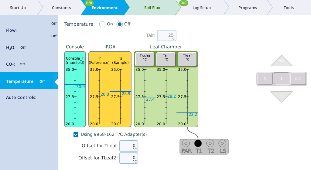
As a result of the cable junctions and length, the adapter cable may cause a temperature measurement offset. The offset should be measured against a standard (such as an ice bath) and entered into the software under Environment > Temperature.
Check the box called Using 9968-162 T/C Adapter(s) and enter the offset in the appropriate field. If the measured value is below the actual temperature, enter a positive number; if the measured value is above the actual temperature, enter a negative number.
None
With this option selected, the system will not measure or record soil temperature.
