Self-calibrating Soil Heat Flux Plates (Hukseflux HFP01SC)

Important: Each output from a multichannel sensor must be configured separately (see Multichannel Sensor).

Table 5‑8. Configuration for self-calibrating soil heat flux plates. The lower set of blocks are used to log the sensitivity of the heat flux plates.
  • Choose from regular or self-calibrating heat flux plates.
  • AIO Module: The Analog In/Out Module to which the sensor leads are connected.
  • AIO Channel: The channel on the module to which the signal is connected.
  • Differential: Whether the signal is differential or single-ended.
  • Sensitivity: Calibration value provided by the manufacturer.
  • Interval (h): Hours between self calibrations.
  • Duration (m): Minutes of the heating during the calibration.
  • Compl Resistor: Resistance (Ohms); set to 10.
  • Rself: Set to Manufacturer's value.
  • Htr DIO Mod/Chan: The module and channel that controls the relay. Check "Shared Relay" if all HFPs use the same relay channel.
  • Htr AIO Chan: This channel reads the resistance.
  • Post cal delay (m): Minutes to delay measurements after the calibration.
  • Schedule: Controls when the software initializes the computation.
  • Schedule Time: An offset that specifies the time at which averaging starts.
  • Schedule Interval: How often averaging occurs.
  • Sample: Controls over the averaging period and interval.
  • Sample Interval: Time between samples.
  • Sample Duration: Duration of the averaging period.
  • Name: Used by the gas analyzer software to identify the variable type and units. See Table 4‑1 to interpret the first number and Table 4‑2 to interpret the second.
  • Prefix: Ignore this field.
  • Suffix: Ignore this field.
  • Right Digits: The number of digits to the right of the decimal (hard stop) for this variable.
  • Name: Recorded in the header of the data file. Default variable names are similar to GHG-Europe standards (see VariableID).
  • Record ID: Tells the datalogger to associate this variable with the Record ID in the LogRec block (see Custom Configurations). It should be the same in both places.
  • Sequence #: The column number in the sequence of variables.
  • Right Digits: Number of digits right of the decimal.
  • Format: The data that is output when logged data is viewed. Typically <val>.
  • Units: The units entered will override previous entries.
  • Click "Units" and enter W/m^2.
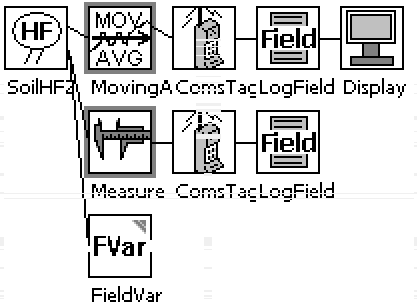
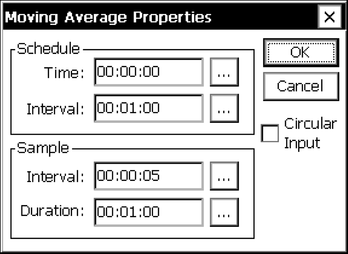
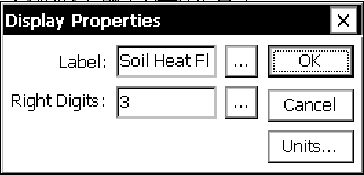
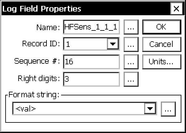
The Display block is used select data that gets displayed on the I2C Display. The data displayed is the last measured value for the block connected to the display block. The data is displayed at the requested precision (right digits) with the selected Label.
  • Time: Controls when the software initializes the computation.
  • Interval: Resolution of the output. 00:01:00 instructs the datalogger to output 1 minute totals.
  • Name: Used by the gas analyzer software to identify the variable type and units. See Table 4‑1 to interpret the first number and Table 4‑2 to interpret the second.
  • Prefix: Ignore this field.
  • Suffix: Ignore this field.
  • Right Digits: The number of digits to the right of the decimal (hard stop) for this variable.
  • Name: Recorded in the header of the data file. Default variable names are similar to GHG-Europe standards (see VariableID).
  • Record ID: Tells the datalogger to associate this variable with the Record ID in the LogRec block (see Custom Configurations). It should be the same in both places.
  • Sequence #: The column number in the sequence of variables.
  • Right Digits: Number of digits right of the decimal.
  • Format: The data that is output when logged data is viewed. Typically <val>.
  • Units: The units entered will override previous entries.
  • Units are uV/W/m^2.
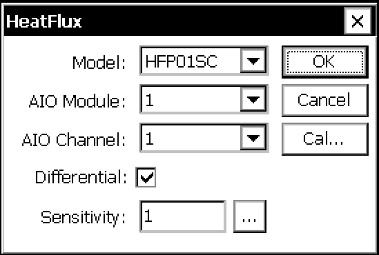
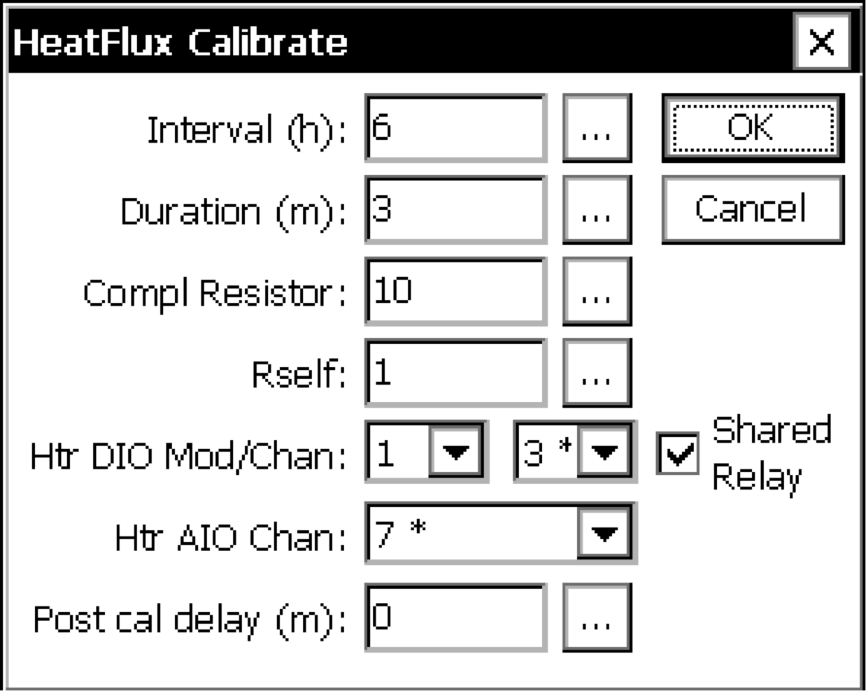
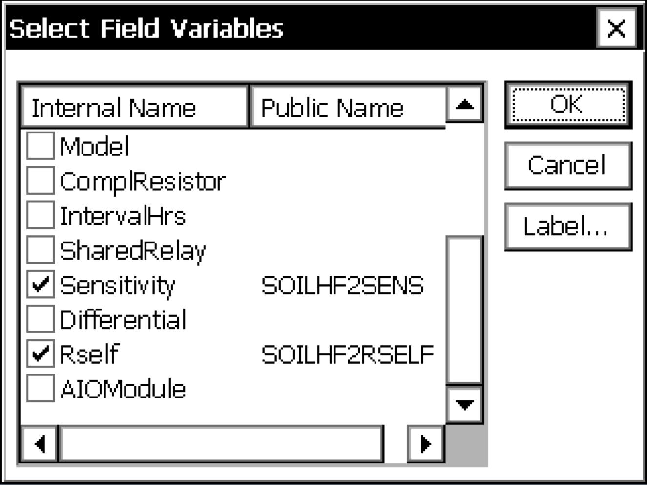
Select Sensitivity and Rself for the self-calibrating soil heat flux plates.

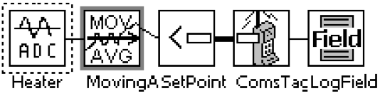
Soil Heat Flux Plate Heater Indicator

This configuration records in the data file when the HFP01SC is undergoing a calibration.

Table 5‑9. Configuration to log whether the heater is on or off.
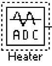
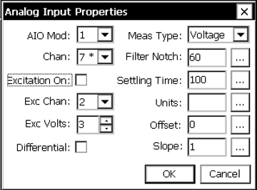
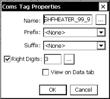
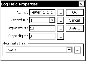
Voltage measurement of module 1, channel 7 (SHF1 heater).
  • Schedule: Controls when the software initializes the computation.
  • Schedule Time: An offset that specifies the time at which averaging starts.
  • Schedule Interval: How often averaging occurs.
  • Sample: Controls over the averaging period and interval.
  • Sample Interval: Time between samples.
  • Sample Duration: Duration of the averaging period.
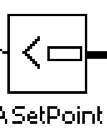
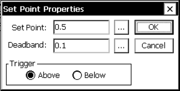
Checks to see if heater voltage is above 0.5 volts. If it is above 0.5 V, sets the output to 1. 1 = soil heat flux plate heater is turned on (calibration is occurring);
0 = typical operation (heater off, not calibrating).
  • Name: Used by the gas analyzer software to identify the variable type and units. See Table 4‑1 to interpret the first number and Table 4‑2 to interpret the second.
  • Prefix: Ignore this field.
  • Suffix: Ignore this field.
  • Right Digits: The number of digits to the right of the decimal (hard stop) for this variable.
  • Name: Recorded in the header of the data file. Default variable names are similar to GHG-Europe standards (see VariableID).
  • Record ID: Tells the datalogger to associate this variable with the Record ID in the LogRec block (see Custom Configurations). It should be the same in both places.
  • Sequence #: The column number in the sequence of variables.
  • Right Digits: Number of digits right of the decimal.
  • Format: The data that is output when logged data is viewed. Typically <val>.
  • Units: The units entered will override previous entries.