Soil Heat Flux Plates (Hukseflux HFP01)

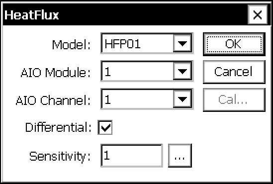
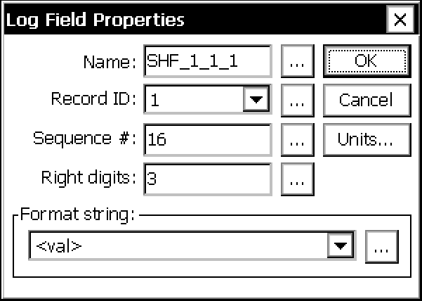
Important: Each output from a multichannel sensor must be configured separately (see Multichannel Sensor).

Table 5‑10. Configuration for soil heat flux plates. The lower set of blocks are used to enter the sensitivity of the heat flux plates.
  • Model: Choose from regular or self-calibrating heat flux plates.
  • AIO Module: The Analog In/Out Module to which the sensor leads are connected.
  • AIO Channel: The channel on the module to which the signal is connected.
  • Differential: Whether the signal is differential or single-ended.
  • Sensitivity: Calibration value provided by the manufacturer.
  • Schedule: Controls when the software initializes the computation.
  • Schedule Time: An offset that specifies the time at which averaging starts.
  • Schedule Interval: How often averaging occurs.
  • Sample: Controls over the averaging period and interval.
  • Sample Interval: Time between samples.
  • Sample Duration: Duration of the averaging period.
  • Name: Used by the gas analyzer software to identify the variable type and units. See Table 4‑1 to interpret the first number and Table 4‑2 to interpret the second.
  • Prefix: Ignore this field.
  • Suffix: Ignore this field.
  • Right Digits: The number of digits to the right of the decimal (hard stop) for this variable.
  • Name: Recorded in the header of the data file. Default variable names are similar to GHG-Europe standards (see VariableID).
  • Record ID: Tells the datalogger to associate this variable with the Record ID in the LogRec block (see Custom Configurations). It should be the same in both places.
  • Sequence #: The column number in the sequence of variables.
  • Right Digits: Number of digits right of the decimal.
  • Format: The data that is output when logged data is viewed. Typically <val>.
  • Units: The units entered will override previous entries.
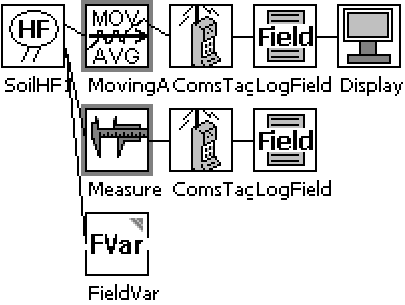
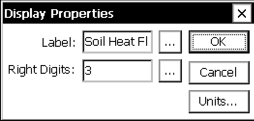
The Display block is used select data that gets displayed on the I2C Display. The data displayed is the last measured value for the block connected to the display block. The data is displayed at the requested precision (right digits) with the selected Label.
  • Click "Units" and enter W/m^2.
  • Time: Controls when the software initializes the computation.
  • Interval: Resolution of the output. 00:01:00 instructs the datalogger to output 1 minute totals.
  • Name: Used by the gas analyzer software to identify the variable type and units. See Table 4‑1 to interpret the first number and Table 4‑2 to interpret the second.
  • Prefix: Ignore this field.
  • Suffix: Ignore this field.
  • Right Digits: The number of digits to the right of the decimal (hard stop) for this variable.
  • Name: Recorded in the header of the data file. Default variable names are similar to GHG-Europe standards (see VariableID).
  • Record ID: Tells the datalogger to associate this variable with the Record ID in the LogRec block (see Custom Configurations). It should be the same in both places.
  • Sequence #: The column number in the sequence of variables.
  • Right Digits: Number of digits right of the decimal.
  • Format: The data that is output when logged data is viewed. Typically <val>.
  • Units: The units entered will override previous entries.
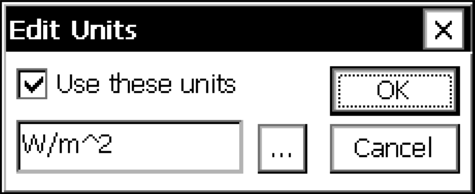
Tells the datalogger to use the entered calibration value for this sensor.