CNF4 Ventilation Unit
The optional CNF4 Heating and Ventilation Unit (LI-COR part number 7900-145) is used to prevent condensation or frost buildup on the CNR4 pyrgeometer windows and pyranometer domes. Condensation on the pyrgeometer windows will absorb far-infrared radiation and lead to measurement errors. These can be avoided by using the CNF4. See the manufacturer’s documentation for more information.
Note: Due to heat dissipation from the CNF4, measurements of sensor temperature may be less accurate. However, the improvements in accuracy that result from heating will be larger than errors that result from heating.
Components
The CNF4 Heater/Ventilation Unit includes the heater/ventilator, three pan-head machine screws with washers, four flat-head screws, the protective shroud, and the CNF4 power cable.

In addition, the CNF4 installation kit includes:
| Component | Description | Part Number |
|---|---|---|
| 2 Gray DIN Terminals | Positive power supply | 331-12885 |
| 2 Blue DIN Terminals | Ground | 331-12959 |
| 2 Shorting Blocks | For power supply terminals | 331-13646 |
| 2 DIN Relays | Power supply control | 290-14669 |
| 2 DIN End Brackets | To secure the DIN terminals | 331-12922 |
| DIN Terminal Cover | Separate DIN terminal blocks | 331-12825 |
| Wire Leads | 5 11.5 cm 18 gauge red; 1 11.5 cm 18 gauge black; 2 30 cm 20 gauge blue |
Installation
There are three general steps to installing the CNF4 in the Biomet Station:
- Assemble/Install the CNF4;
-
- Configure the heater and ventilator timers.
These are described in the following pages.
- Assemble the CNF4.
- After attaching the temperature and sensor cables to the radiometer, attach the heater/ventilator to the CNR4 body using the three machine screws.
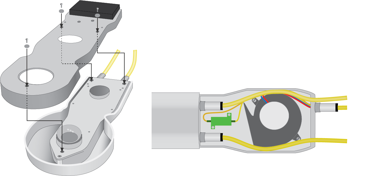
-
- Route the cables around the fan in the ventilator.
- Attach the protective shroud with the remaining four screws.
- Attach the ventilator power cable.
- Install the CNF4 Control Components.
- Gather the CNF4 installation kit components and install them in the enclosure as shown.
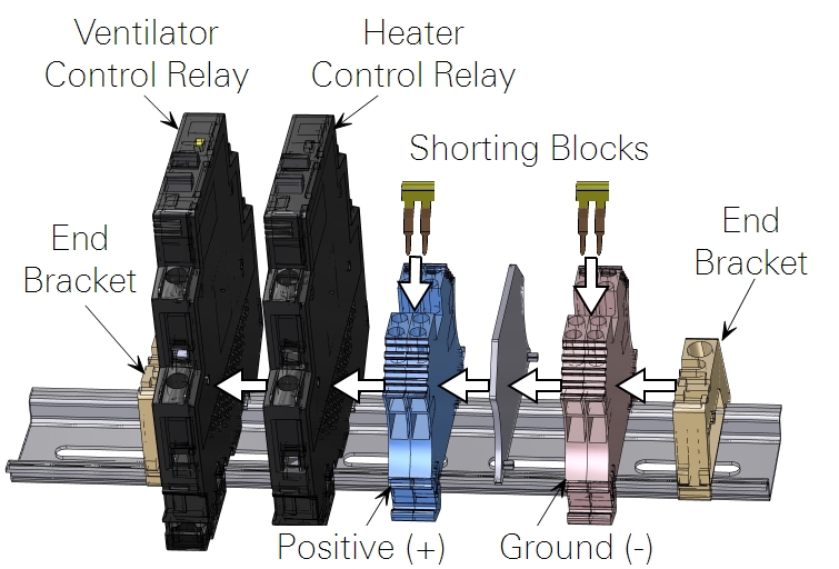
- These components can be installed on the DIN rail to the right or left of the AIO modules or a section of DIN rail in the upper left of the enclosure.
- Install the Power Supply/Controller Wires.
- The power supply and control wires are required to actuate the relays and provide the timer-controlled power supply to the CNF4 heater and ventilator.
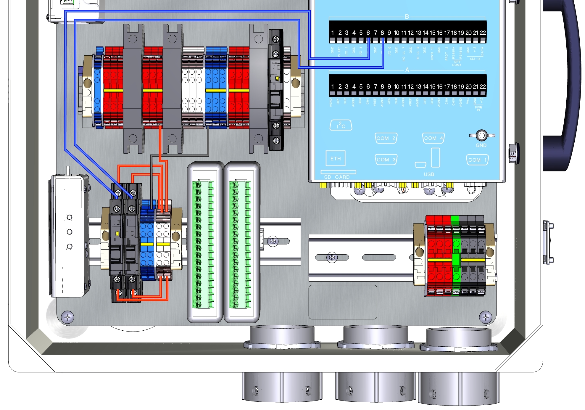
-
Description Wire Lead Terminals Connected CNF4 Power (+) 11.5 cm Red DIN Terminal 14 to Heater Power (+) Terminal CNF4 Power (-) 15 cm Black DIN Terminal 18 to Heater Power (-) Terminal Ventilator Relay Control Signal 30 cm Blue DIO1 Terminal 6 (I/O 4) to Left Relay 4/A2 Ventilator Relay Power 11.5 cm Red DIN Terminal to Left Relay +3/A1 Ventilator Power 11.5 cm Red DIN Terminal to Left Relay +1/L1 Heater Relay Control Signal 30 cm Blue DIO1 Terminal 8 (I/O 5) to Right Relay 4/A2 Heater Relay Power 11.5 cm Red DIN Terminal to Right Relay +3/A1 Heater Power 11.5 cm Red DIN Terminal to Right Relay +1/L1 - Wire the CNF4 to the Controlled Power Supply.
-
Description Color Connection Ventilator (+) Yellow Left Relay 2/T1 Ventilator (-) Brown Blue DIN Terminal Tachometer (+) Green not used Tachometer (-) Gray not used Heater (+) Black Right Relay 2/T1 Heater (+) White Right Relay 2/T1 Heater (-) Red Blue DIN Terminal Heater (-) Blue Blue DIN Terminal Shield (black) Black Blue DIN Terminal 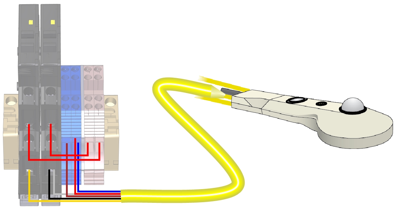
- Configure the Timer Controls.
- The CNF4 Heater and Ventilation Unit is supported by programs Biomet_101 and Biomet_103. Follow the steps below to configure the CNF4:
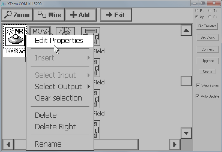
- Select Graphical Setup and click Edit.

- Scroll down to the NetRad configuration block. Click it and select Edit Properties.
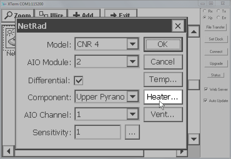
- All fields in the resulting dialog are configured automatically from the previous steps. To set the timer for the heater click the Heater... button.
- Check the Enable Heater box. Then set the Time, Interval, and Duration.
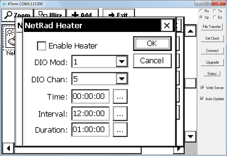
- Time: The time that the heater will be enabled
- Interval: Interval between activations
- Duration: Duration of the activation
- For example, if Time is 19:30:00, the Interval is 24:00:00, and the Duration is 01:30:00, then every 24 hours—at 19:30 (7:30 pm)—the system will power the heater for 1 hour 30 minutes.
- The ventilator is configured similarly, except that it uses DIO Channel 4.
Note: The heater and ventilator are controlled by separate relays so they can be configured independently.
Typically the heater should be on 1 hour before sunset to 1 hour after sunrise. Read the manufacturer's recommendations for more information.